
High-Accuracy Thermometer
The circuit design employs a platinum Resistance Temperature Detector (RTD) configured in a Wheatstone bridge arrangement, which is essential for precise temperature measurement. The current source drives the RTD, allowing for a consistent current flow that generates a voltage proportional to the resistance change of the RTD due to temperature variations. The LT1009 operational amplifier is utilized for its high precision and stability, ensuring minimal drift and noise in the measurements.
The bridge output is sensitive to temperature changes, and the differential amplifier configuration of A3 enhances the signal while simultaneously correcting for any nonlinearity introduced by the RTD. The feedback mechanism through the resistive divider allows for fine-tuning of the output, ensuring that the temperature readings remain accurate across the specified range. This feedback loop is vital for maintaining the integrity of the measurement, especially in applications where precision is critical.
In terms of calibration, it is essential to follow a systematic approach as outlined in the accompanying diagram to ensure that the thermometer operates within its specified accuracy limits. Calibration typically involves comparing the thermometer readings against a known temperature standard and adjusting the feedback network to account for any discrepancies.
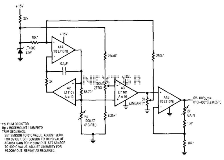
Overall, this circuit exemplifies a sophisticated approach to temperature measurement, integrating advanced components and techniques to achieve high accuracy and reliability in various applications, including industrial and laboratory environments. This circuit combines a current source and a platinum RTD bridge to form a complete high-accuracy thermometer. Th e ground-referred RTD sits in a bridge that is composed of the current drive and the LT1009 biased resistor string. The current drive allows the voltage across the RTD to vary directly with its temperature-induced resistance shift.
The difference between this potential and that of the opposing bridge leg forms the bridge output. The RTD"s constant drive forces the voltage across it to vary with its resistance, which has a nearly linear positive temperature coefficient. The nonlinearity could cause several degrees of error over the circuit"s 0°C -400°C operating range.
The bridge"s output is fed to instrumentation amplifier A3, which provides differential gain, while simultaneously supplying nonlinearity correction. The correction is implemented by feeding a portion of A3"s output back to Al"s input via the 10- to 250-KOhmhm divider.
This causes the current supplied to RP to slightly shift with its operating point, compensating sensor nonlinearity to within ±0.05°C. A1B, providing additional scaled gain, furnishes the circuit output. To calibrate this circuit, follow the procedure given in the diagram. 🔗 External reference
Related Circuits
Related components PDF download: ICL7106CD4036. The LCD electronic thermometer circuit is illustrated. The temperature sensor KTY10 exhibits a strong linear relationship between temperature and resistance. Points A and B (Measurement display circuit) can be connected with a 100-meter wire....
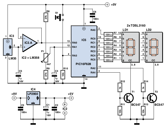
The device is user-friendly and consumes minimal current, allowing it to operate throughout the battery's shelf life. It employs a standard LM35DZ sensor (IC3) whose analog output voltage is buffered by an LM358 (IC2A). The voltage is processed by...
The thermistor network specified eliminates the need for a linearity trim at the expense of accuracy and operational range. The thermistor network is designed to provide a simplified approach to temperature measurement and compensation by negating the requirement for linearity...
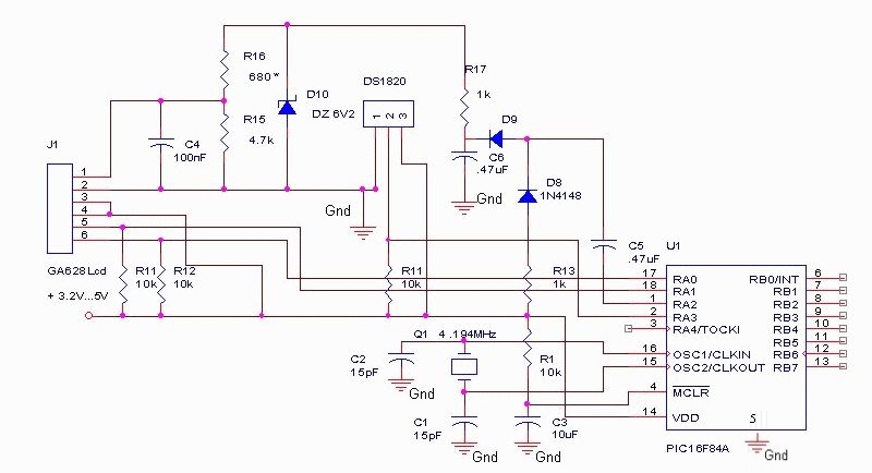
The DS18S20 digital thermometer offers a precision of 0.5 °C, with the SCRATCHPAD being read every 800 ms. Capacitors C5 and C6, along with diodes D8 and D9, form a voltage doubler to power the LCD panel. The DS18S20...

The following circuit is a PC thermometer utilizing the DS1621. Features include the ability to plug into any available PC COM port, a temperature range of -20 to 125°C, and the capability to display temperatures in both Celsius (°C)...
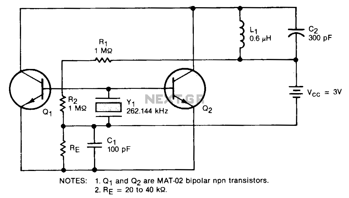
This circuit is designed for precise measurement of temperature in degrees Celsius. It includes a transmitter section that converts the output voltage from the sensor, which is proportional to the temperature being measured, into a frequency signal. This frequency...