
LCD electronic thermometer circuit
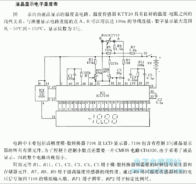
The LCD electronic thermometer circuit employs the ICL7106CD4036 integrated circuit, which is designed for digital temperature measurement applications. The KTY10 temperature sensor is a vital component, known for its accurate and linear resistance-temperature characteristics, making it suitable for precise temperature readings.
In this circuit, the KTY10 sensor converts temperature variations into corresponding resistance changes, which are then processed by the ICL7106. The ICL7106 is a dual-slope analog-to-digital converter that provides high accuracy and stability in measuring the analog voltage output from the KTY10 sensor.
The measurement display circuit, which can be placed up to 100 meters away from the sensor, utilizes a 3-wire connection to minimize signal degradation over distance. This configuration ensures that the digital output remains accurate despite the extended wiring.
The digital display of the thermometer is capable of showing temperatures in the range of -50°C to +150°C, making it suitable for various applications, including environmental monitoring, HVAC systems, and industrial processes. The LCD screen provides a clear and easy-to-read output, which enhances user interaction and data interpretation.
Overall, this electronic thermometer circuit combines precision sensing, effective signal processing, and user-friendly display features, making it a robust solution for temperature measurement needs.Related components PDF download: ICL7106CD4036 The LCD electronic thermometer The LCD electronic thermometer circuit is as shown. The temperature sensor KTY10 has good linear relationship between temperature - resistance, and you can connect point A and point B (Measurement display circuit) with 100m wire, the digital display range is -50?
to +150?, the.. 🔗 External reference
Related Circuits

For variable-frequency operation, Rl and R2 can be replaced by a dual potentiometer. In electronic circuits that require variable-frequency operation, the use of a dual potentiometer as a replacement for resistors Rl and R2 can provide enhanced functionality and flexibility....
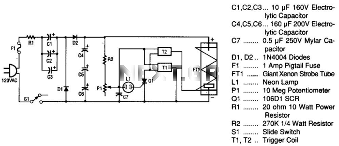
This strobe light operates from standard 120-Vac power. Resistor R1 limits the amount of current applied to the voltage doubler stage, which consists of capacitors C1, C2, C3, and diodes D1, D2, along with capacitors C4, C5, and C6....
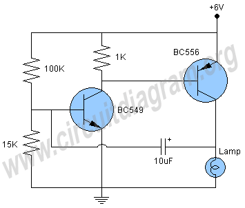
This is a simple two-transistor lamp flasher circuit that can be used to flash a 6-volt lamp. The circuit is compact and can be easily fitted into a small enclosure. It utilizes two transistors: one is an NPN BC549,...

The CMOS amplifier is biased into the linear region by resistor RB. The pi-type crystal network (C1 and C2, and XTAL) provides the 180-degree phase shift at the resonant frequency, which causes the circuit to oscillate. The described circuit utilizes...
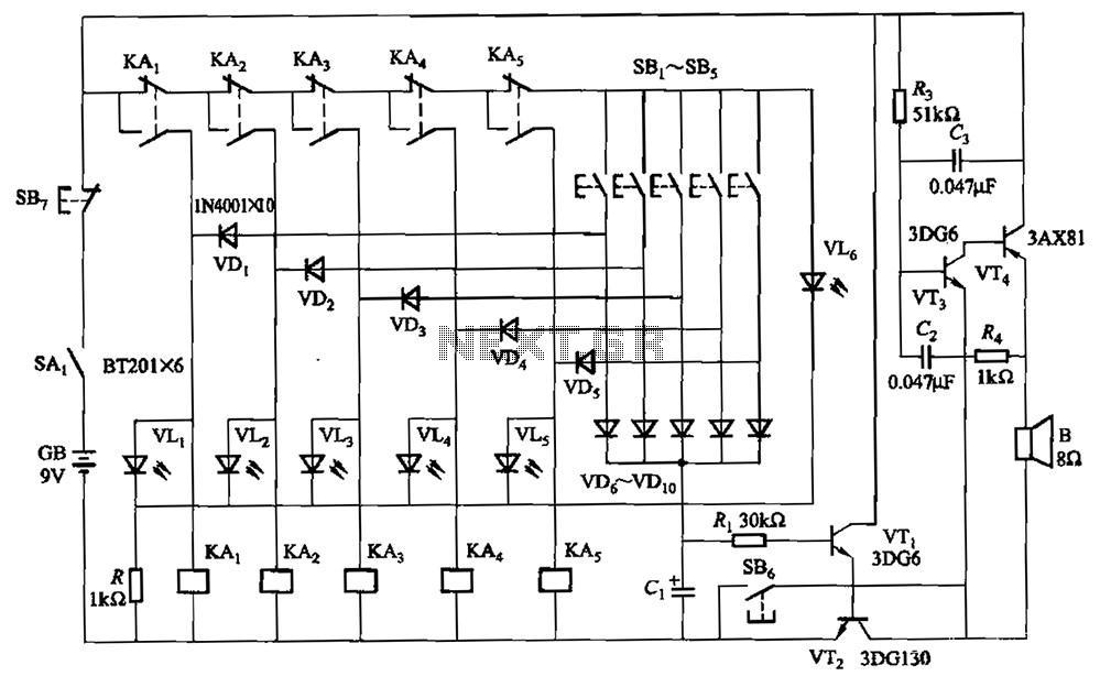
A relay-style circuit designed for a five electronic responder group. This circuit features self-locking capabilities, sound and light displays, time monitoring, and additional functions. The circuit includes a monitoring time button operated by the moderator. When this button is...
All distances mentioned can vary depending on the infrared transmitting and receiving LEDs used and are significantly affected by the color of the reflecting surface. Black surfaces greatly reduce the device's sensitivity. This circuit can also be applied in...