
high current 10 to 20 amp automatic
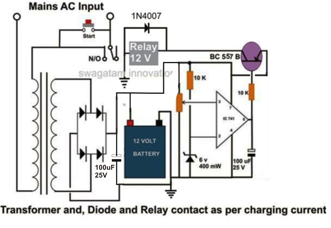
This battery charging circuit design is structured around a bridge rectifier that converts AC voltage from a transformer into DC voltage suitable for battery charging. The inclusion of a 1000uF/25V capacitor across the bridge output enhances the smoothing of the rectified voltage, reducing ripple and providing a more stable DC output for effective charging.
The op-amp 741 is utilized as a voltage comparator, where its non-inverting input is connected to a voltage divider that sets the reference voltage corresponding to the fully charged state of the battery. When the battery voltage exceeds this reference, the op-amp output changes state, which is critical for controlling the relay and thus the charging process. The relay acts as a switch that can handle the high current required for charging large batteries, ensuring that the circuit can manage the load without overheating or failing.
The initial activation of the circuit through the "start" switch is a crucial design feature, allowing for manual control of the charging process. This mechanism ensures that the system does not inadvertently start charging when it is not intended, providing an additional layer of safety. The latching relay maintains power to the charging circuit, allowing it to operate independently of the start switch once engaged.
In summary, this circuit is designed to automatically manage the charging of high-capacity lead-acid batteries, ensuring safety and efficiency through careful voltage monitoring and control. The implementation of key components, such as the bridge rectifier, filter capacitor, op-amp comparator, and relay, collectively contribute to a reliable and effective battery charging solution.This design can be used for charging high current lead acid batteries in the order of 100 to 200 AH, the design is perfectly automatic and switches of the power to the battery and also itself, once the battery gets fully charged. A filter capacitor after the bridge network has been ignored for the sake of simplicity, however for better DC outp
ut to the battery one can add a 1000uF/25V capacitor across the bridge positive and negative. The next stage consists of an opamp 741 IC voltage comparator, which is configured to sense the battery voltage while it is being charged and switch its output at pin #6 with the relevant response. The preset is adjusted such that the IC reverts its output at pin #6 when the battery becomes fully charged and reaches about 14 volts which happens to be the transformer voltage at normal conditions.
Initially, power to the circuit is initiated by pressing the "start" switch. On doing this, the switch bypasses the contacts of the relay and powers the circuit momentarily. This switches ON the transistor and the relay, the relay instantly latches the power via its relevant contacts such that now even if the "start" switch is released, the circuit remains switched ON and begins charging the connected battery. The circuit gets completely switched OFF until the start button is pressed once again and the connected battery has a charge that`s under the set 14 volt mark.
Switch ON power by pressing the start button and keep it depressed manually, simultaneouslyadjust the preset such that the relay just trips or switches OFF at the given rated transformer voltage which should be around 14 volts. Due to the discharged battery, now the voltage to the circuit will drop under 14 volts and the circuit will instantly latch, initiating the procedure as explained in the above section.
🔗 External reference
Related Circuits
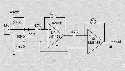
This circuit utilizes an LM1458 dual operational amplifier integrated circuit (IC) to amplify audio signals from a condenser microphone. The amplified output allows the microphone to interface with devices that typically do not accept microphone-level signals. The circuit operates...
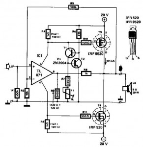
This audio power amplifier employs two complementary MOSFETs (IRF9520 and IRF520) to provide up to 20W output into an 8-ohm speaker. A TL071 operational amplifier functions as the input amplifier. The MOSFETs require heatsinking with a thermal resistance of...
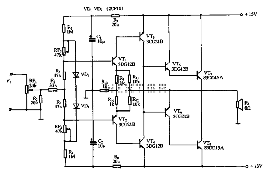
The circuit utilizes diode VDi, f Pooh to stabilize the base bias of transistors VTi and VT2, ensuring a more stable quiescent point when the supply voltage is within a specific range. In the event of temperature fluctuations, the...
Explore the power amplifier integrated circuit from National Semiconductor, the LM4780. What is noteworthy about this component is its very low harmonic distortion. Typically, manufacturers specify the maximum power of their products with a harmonic content of around 10%....
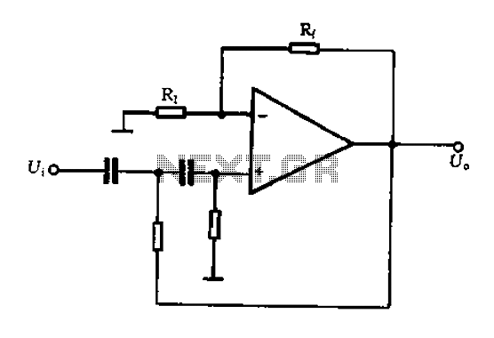
The Bong ordinary differential amplifier circuit differs from a standard differential circuit by incorporating a voltage-current conversion circuit, which consists of resistors R and Rl. The operational amplifier (OP amp) includes a voltage divider that subsequently converts the voltage...
A typical two high-pass filter circuit. A high-pass filter (HPF) is an electronic circuit that allows signals with a frequency higher than a certain cutoff frequency to pass through while attenuating signals with frequencies lower than the cutoff frequency. A...
Warning: include(partials/cookie-banner.php): Failed to open stream: Permission denied in /var/www/html/nextgr/view-circuit.php on line 713
Warning: include(): Failed opening 'partials/cookie-banner.php' for inclusion (include_path='.:/usr/share/php') in /var/www/html/nextgr/view-circuit.php on line 713