
High-frequency crystal oscillator

This configuration can be accurately constructed using 2.5 ns delay lines for the 200 MHz output or can be approximated with the two MC10101 gates, which are simpler to integrate and introduce minimal skew in the output signal duty cycle. The MC1662 gates combine the four-phase 100 MHz signals as depicted in Figure B. The outputs of the MC1662 gates are wire-OR connected to generate the 200 MHz signal. MECL III gates are selected due to their capability to handle the bandwidth requirements for 200 MHz signals. Additionally, one of the remaining MC1662 gates serves as a VBB bias generator for the oscillator. By linking the NOR output back to the input, the circuit stabilizes at the midpoint of the logic swing, or at VBB. A 0.001 µF capacitor is included to prevent oscillation within the VBB circuit.
The schematic design includes the following components and their interconnections:
1. **MC10101 Crystal Oscillator Configuration**:
- One MC10101 gate is configured as a crystal oscillator, with a crystal connected in series with the feedback loop. The LC tank circuit is tuned to resonate at 100 MHz, ensuring stable oscillation at the desired frequency.
2. **Buffer Stage**:
- A second MC10101 gate buffers the output of the crystal oscillator, providing complementary outputs that maintain the integrity of the 100 MHz signal.
3. **Frequency Doubler Circuit**:
- The frequency doubler consists of two MC10101 gates that act as phase shifters, along with two MC1662 NOR gates. The phase shifters introduce the necessary delay to achieve a 90° phase difference, allowing for the generation of a 200 MHz signal with a 50% duty cycle.
4. **Combining Outputs**:
- The outputs from the MC1662 gates are wire-OR connected to create the final 200 MHz output signal. This method ensures that the combined output retains the necessary signal characteristics.
5. **Bias Generation**:
- One MC1662 gate is utilized as a VBB bias generator, stabilizing the circuit by connecting the NOR output to the input. This configuration allows the oscillator to operate within the optimal voltage range, ensuring reliable performance.
6. **Capacitance for Stability**:
- A 0.001 µF capacitor is connected to the VBB circuit to filter out any potential oscillations, thereby enhancing the stability of the oscillator circuit.
Overall, this high-speed oscillator design effectively combines crystal oscillation principles with modern digital logic components to achieve precise frequency generation suitable for high-frequency applications.A high speed oscillator is possible by combining an MECL 10 crystal oscillator with an MECL III frequency doubler as shown. One section of the MC10101 is connected as a 100 MHz crystal oscillator with the crystal in series with the feedback loop.
The LC tank circuit tunes the 100 MHz harmonic of the crystal and may be used to calibrate the circuit to the exact frequency. A second section of the MC10101 buffers the crystal oscillator and gives complementary 100 MHz signals.
The frequency doubler consists of two MC10101 gates as phase shifters and two MC1662 NOR gates. For a 50% duty cycle at the output, the delay to the true and complement 100 MHz signals should be 90°. This may be built precisely with 2.5 ns delay lines for the 200 MHz output or approximated by the two MC10101 gates. The gates are easier to incorporate and cause only a slight skew in output signal duty cycle. The MCI662 gates combine the 4 phase 100 MHz signals as shown in Figure B. The outputs of the MC1662's are wire-OR connected to give the 200 MHz signal. MECL III gates are used because of the bandwidth required for 200 MHz signals. One of the remaining MC1662 gates is used as a VBB bias generator for the oscillator. By connecting the NOR output to the input, the circuit stays in the center of the logic swing or at VBB.
A 0.001 µ¥ capacitor ensures the VBB circuit does not oscillate.
Related Circuits
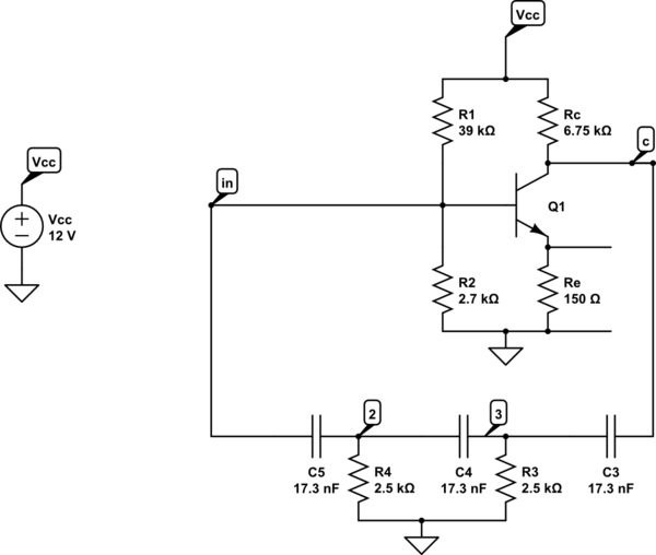
A phase shift oscillator utilizing a common emitter (CE) amplifier. The circuit operates with a collector voltage (Vc) of approximately 6V and achieves a gain of around 40, exceeding the minimum requirement of 29. The target oscillation frequency is...
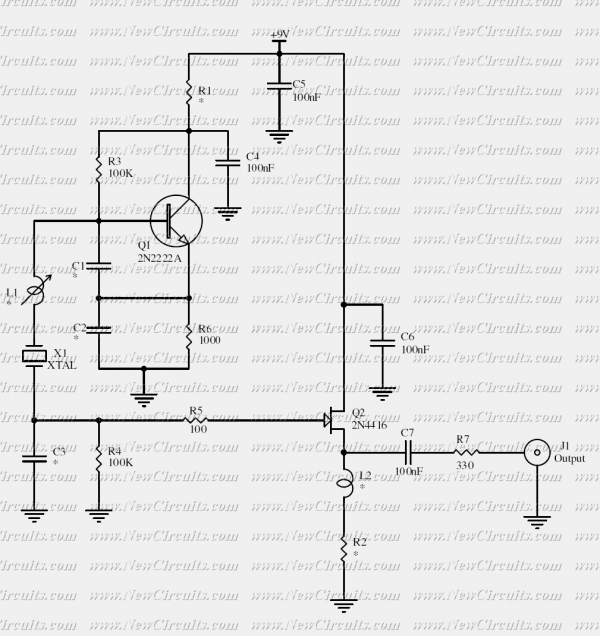
This crystal oscillator is designed to operate with fundamental crystals with less than 1 mW dissipated in the crystal. The signal current is filtered by the crystal and develops a voltage across a capacitor with about 500 ohm of...
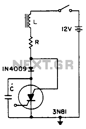
A positive transient, such as the power switch closing, charges through L to a voltage above the supply voltage, if Q is sufficient. When the current reverses, the diode blocks and triggers the SCS. As the capacitor discharges, the...
A simple crystal oscillator can be constructed using a comparator from the LT1720/LT1721 series; however, this design may encounter several inherent limitations and issues. While the LT1720/LT1721 provides the correct logic output when one input falls outside the common...
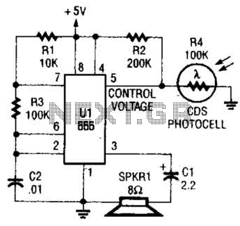
This circuit can be utilized as a light detector and potentially as a tool for individuals with visual impairments. The frequency of the oscillator is influenced by the level of illumination received by LDR4. The circuit operates by employing a...
Colpitts oscillators are similar to the shunt-fed Hartley circuit; however, the Colpitts oscillator uses two series capacitors in its LC circuit instead of a tapped inductor. The connection between these two capacitors serves as the center tap for the...