
capacitor Whats wrong with this Phase Shift Oscillator

The phase shift oscillator is a type of electronic oscillator that generates a sine wave output by utilizing the phase shift provided by passive components in conjunction with an active amplifier. In this configuration, a common emitter amplifier is employed, which provides the necessary gain and phase shift to sustain oscillations.
The circuit typically consists of three RC (resistor-capacitor) stages, each contributing a phase shift of 60 degrees, totaling a 180-degree phase shift. This phase shift is complemented by an additional 180-degree phase shift provided by the common emitter amplifier, resulting in a total phase shift of 360 degrees, which is essential for oscillation.
Key components include:
1. **Common Emitter Amplifier**: The transistor operates in the active region, providing voltage gain. The collector voltage (Vc) is set to approximately 6V, which is optimal for the transistor's operation and ensures sufficient headroom for the output signal.
2. **Resistors and Capacitors**: The values of the resistors and capacitors in the RC network are chosen to set the desired oscillation frequency of 1.5 kHz. The frequency can be calculated using the formula:
\[
f = \frac{1}{2\pi R_{total}C_{total}}
\]
where \(R_{total}\) is the equivalent resistance of the resistors in the network and \(C_{total}\) is the total capacitance.
3. **Feedback Loop**: The output of the amplifier is fed back to the input through the RC network, which ensures that the oscillation condition is met. The gain of the amplifier must be greater than 29 to maintain oscillations, and in this design, it is set to approximately 40, providing a robust margin for stability.
4. **Power Supply**: The circuit requires a suitable DC power supply to provide the necessary voltage for the amplifier. The choice of components must account for the power supply voltage to ensure proper operation without distortion of the output waveform.
In summary, this phase shift oscillator design effectively combines the common emitter amplifier with a carefully calculated RC network to achieve stable oscillations at the desired frequency of 1.5 kHz, with adequate gain and phase conditions met for sustained operation.A phase shift oscillator, using a CE Amplifier. I have a Vc of approximately 6V, gain of approximately 40(>29, as required). I aim for an oscillation frequency of 1. 5 kHz. 🔗 External reference
Related Circuits
A PLL (Phase-Locked Loop) oscillator is utilized to achieve a very stable frequency with minimal distortion in the sine wave output. Its stability is comparable to that of crystal-based oscillators, while the distortion level of the sine wave output...
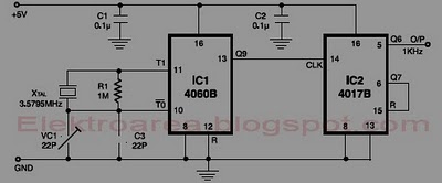
This circuit is designed for accurate time-base generation utilizing the commonly available 3.5795 MHz crystal, which is frequently used in telecommunication equipment. A crystal-based oscillator combined with a divider IC chain or a similar circuit, such as an ASIC,...
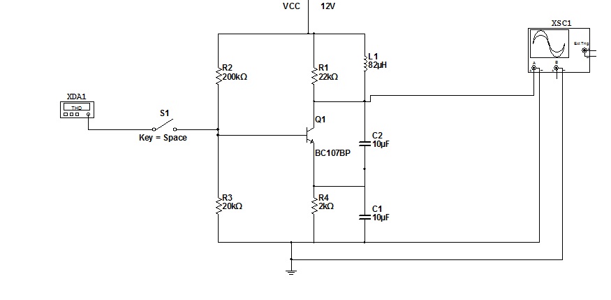
To simulate this circuit, NI Multisim produced by National Instruments is required. The oscillator will generate a stable waveform. If a file needs to be saved, navigate to the source code. It is important to use Multisim version 11....
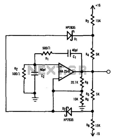
The HA2541 is ideal for use as the core component of an oscillator. Despite the basic diode limiting provided by R3 through R7 and D1 and D2, a high-quality sine wave at 40 MHz can be easily achieved, with...
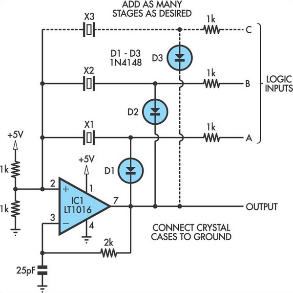
This oscillator circuit allows crystals to be electronically switched through logic commands. The circuit is best comprehended by initially disregarding all crystal components. The oscillator circuit described functions as a frequency generator that utilizes the properties of quartz crystals to...
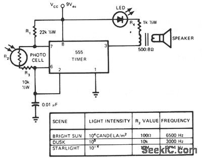
This circuit's frequency of oscillation increases directly with light intensity. The greater the light intensity, the higher the frequency of the oscillator. The 555 timer operates in astable oscillator mode, where frequency and duty cycle are controlled by two...