
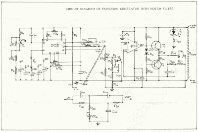
Light-Controlled Oscillator Circuit
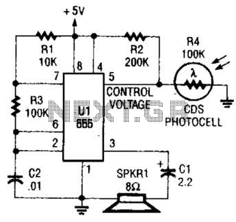
The circuit operates by employing a Light Dependent Resistor (LDR), specifically LDR4, which serves as the primary sensor for light detection. The resistance of LDR4 decreases with increasing light intensity, allowing it to effectively monitor ambient light levels. The circuit is designed to convert the varying resistance of the LDR into a corresponding frequency output through an oscillator configuration.
In this setup, the LDR is integrated into an oscillator circuit, which may include components such as operational amplifiers, resistors, and capacitors. As light levels change, the resistance of LDR4 alters the charging and discharging rates of the capacitor in the oscillator circuit, thereby modifying the frequency of the output signal. This output can be used to trigger other devices or systems, providing feedback to the user about the surrounding light conditions.
For applications aimed at assisting visually impaired individuals, the circuit can be further enhanced with audio feedback mechanisms. For instance, a speaker or buzzer can be connected to the output of the oscillator, producing sound signals that vary in pitch or frequency based on the detected light levels. This auditory feedback can help users navigate their environment by indicating whether the area is well-lit or dimly lit.
In summary, this light detection circuit leverages the properties of LDR4 to provide a variable frequency output that can be utilized in various applications, particularly in enhancing the mobility and awareness of visually impaired users. The design can be adapted with additional components to improve functionality and user experience, making it a versatile tool in assistive technology. This circuit can be used as a light detector and possibly as an aid for the visually handicapped. The frequency of the oscillator is determined by the amount of illumination striking LDR4. 🔗 External reference
Related Circuits
The circuit described below is notable for its low power consumption. With a 9V input and no load at the output, it draws only 50 mA, which is significantly lower than the quiescent current of a 78L05 regulator. The...
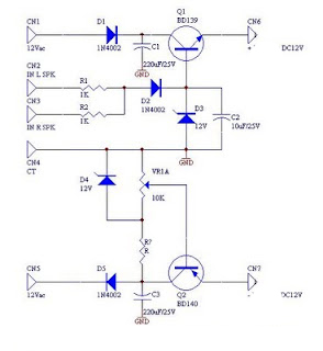
DC fan control circuit for a power amplifier. It features a variable speed DC fan that operates based on the input signal. The speed of the fan's rotation is dependent on the amplitude of the input signal received from...
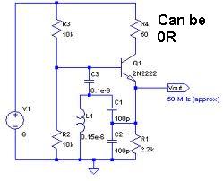
An oscillator circuit capable of generating a high-quality sine wave with a frequency of at least 500 MHz, intended for RFID applications. There have been attempts to utilize a class E oscillator, but the design has not yet been...
Power pulse circuit using LM350 and NE555. This circuit can be used to drive lamps, power LEDs, DC motors, etc. Adjust R5 for output amplitude and R1 for output power. The LM350 is an adjustable 3-terminal voltage regulator. The power...
This circuit was designed to drive an impact counter, utilizing the ICL8038 as its core component. It is intended for a motor that operates a conveyor, with the motor featuring a feedback system known as a tachogenerator. Only a...
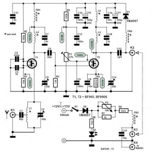
Along with a suitable directional antenna, this high-performance two-stage antenna amplifier for the VHF FM broadcast band will allow for the reception of distant signals. This two-stage antenna amplifier is designed to enhance signal reception in the VHF FM broadcast...
Warning: include(partials/cookie-banner.php): Failed to open stream: Permission denied in /var/www/html/nextgr/view-circuit.php on line 713
Warning: include(): Failed opening 'partials/cookie-banner.php' for inclusion (include_path='.:/usr/share/php') in /var/www/html/nextgr/view-circuit.php on line 713