
High Frequency Generator Circuit
The high-frequency waveform generator circuit typically employs operational amplifiers (op-amps) or specialized waveform generator ICs to create various waveforms. The core of the circuit consists of a feedback loop that determines the frequency and amplitude of the output signal.
To generate a sine wave, the circuit may utilize a Wien bridge oscillator configuration, which includes resistors and capacitors to set the frequency while maintaining stability. The output can be adjusted using variable resistors or potentiometers to fine-tune the amplitude and frequency of the sine wave.
For generating triangle and square waves, the circuit can incorporate a Schmitt trigger or a comparator. By feeding the output of the sine wave generator into the comparator, the circuit can produce a square wave by switching the output high and low at the peak and trough of the sine wave. To create a triangle wave, an integrator circuit can be used in conjunction with the square wave output, converting the square wave into a linear ramp signal.
The power supply for this circuit typically requires a dual supply voltage to accommodate the op-amps or waveform generator ICs, ensuring that the output can swing positively and negatively around a reference point. Proper decoupling capacitors should be placed close to the power supply pins of the components to filter any noise and ensure stable operation.
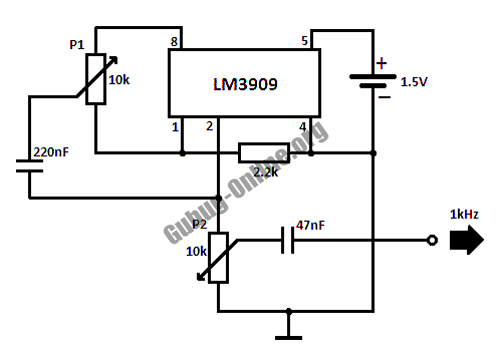
Overall, this high-frequency waveform generator circuit offers versatility and adaptability for various electronic applications, making it an essential tool for engineers and hobbyists alike.This is a design circuit for high frequency waveform generator is very useful in electronic experiment and design. This circuit is generate sine wave oscillation, but actually we can modify the circuit to generate triangle or square wave function.
Th .. 🔗 External reference
Related Circuits
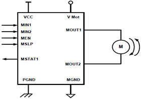
The schematic presented illustrates a 5A H-Bridge Module designed for the operation of a single Bipolar DC motor. The H-Bridge Module includes a header set (J2) and a connector terminal set (J1). Below is the pinout description for the...
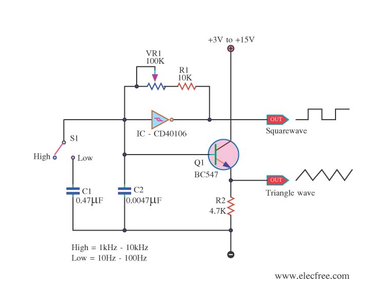
This is a circuit function generator that produces triangle and square wave signals. It utilizes an IC 40106 and a BC547 transistor. The variable resistor VR1 is used to control the frequency output, while switch S3 serves as a...

This is a simple design of an audio level meter. The circuit utilizes a single integrated circuit (IC) and a minimal number of external components. It is based on the LM3915, which functions as the controller for the audio...
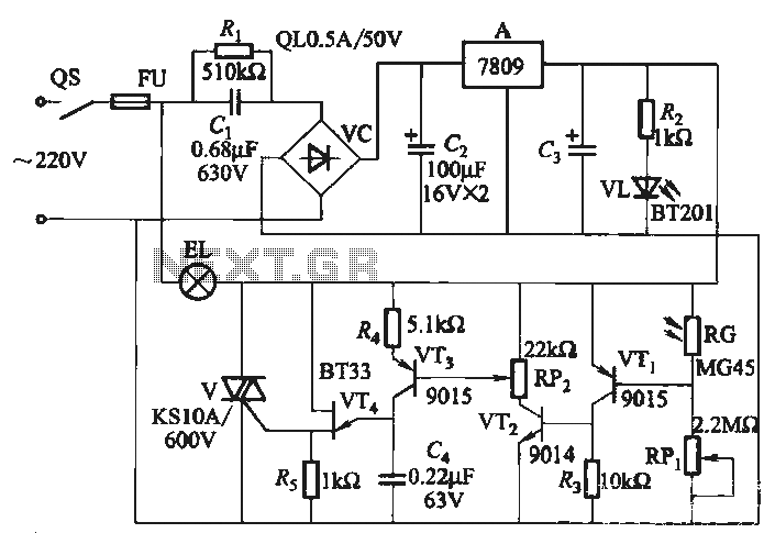
EL auxiliary lights. When the lights dim in the ballroom, EL automatic lights, and ballroom lights dim in a more serious manner. EL light becomes brighter, allowing the inner disco lighting to automatically maintain a certain brightness. A photoresistor...
In addition to its primary function as a headphone amplifier, the circuit is suitable for various applications requiring a wide bandwidth low power amplifier. It is constructed using an operational amplifier (op-amp), with its output current enhanced by a...
This FM RF power amplifier circuit is constructed using a BLY94 transistor, which can deliver up to 50W at a frequency of 175MHz with a power gain of 7dB, resulting in approximately 5 times power amplification. However, in this...
Warning: include(partials/cookie-banner.php): Failed to open stream: Permission denied in /var/www/html/nextgr/view-circuit.php on line 713
Warning: include(): Failed opening 'partials/cookie-banner.php' for inclusion (include_path='.:/usr/share/php') in /var/www/html/nextgr/view-circuit.php on line 713