
Triangle and Squarewave Generator by IC 40106
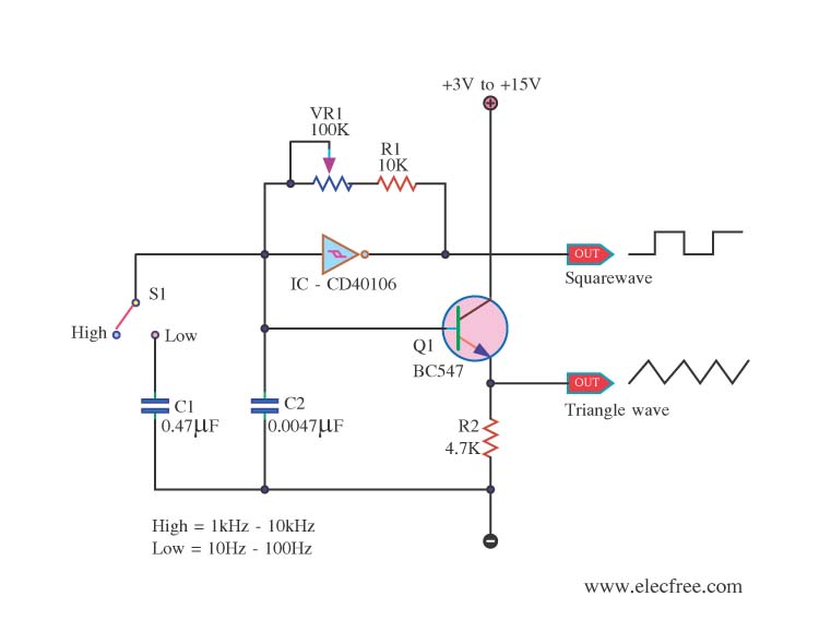
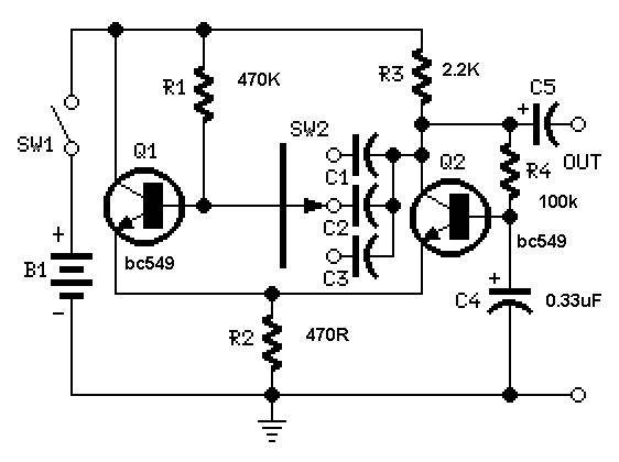
The circuit function generator is designed to create two types of waveforms: triangle and square waves, which are commonly used in various electronic applications such as signal processing, testing, and waveform generation. The heart of the circuit is the IC 40106, a Schmitt trigger inverter that provides the necessary switching characteristics for generating these waveforms.
The configuration of the circuit involves connecting the IC 40106 in a feedback loop to form an oscillator. The output of the inverter is fed back to its input through a resistor-capacitor (RC) network, which determines the frequency of oscillation. The capacitor's charge and discharge times create the triangular waveform, while the sharp transitions of the Schmitt trigger produce the square wave.
The BC547 transistor is employed to amplify the output signals, ensuring that the generated waveforms can drive other components or circuits effectively. The variable resistor VR1 allows for fine-tuning of the frequency output by adjusting the resistance in the RC network, providing flexibility in waveform generation.
Switch S3 is implemented to select between the triangle and square wave outputs, enabling the user to choose the desired waveform for their specific application. This selector switch facilitates easy operation and enhances the versatility of the circuit.
Overall, this circuit function generator serves as a valuable tool for engineers and hobbyists alike, providing reliable waveform generation with adjustable frequency and selectable output types.This is circuit Function Generater,Triangle and Squarewave Generator. Use IC 40106 and Transistor BC547. VR1 For Control frequency Output. S3 to Seclector. 🔗 External reference
Related Circuits
The circuit below demonstrates how to construct a DAQ_LITE device, accompanied by an image of the finished PCB board. It is important to note that the 80mA fuse depicted in the image and the nearby protection diode are recommended...
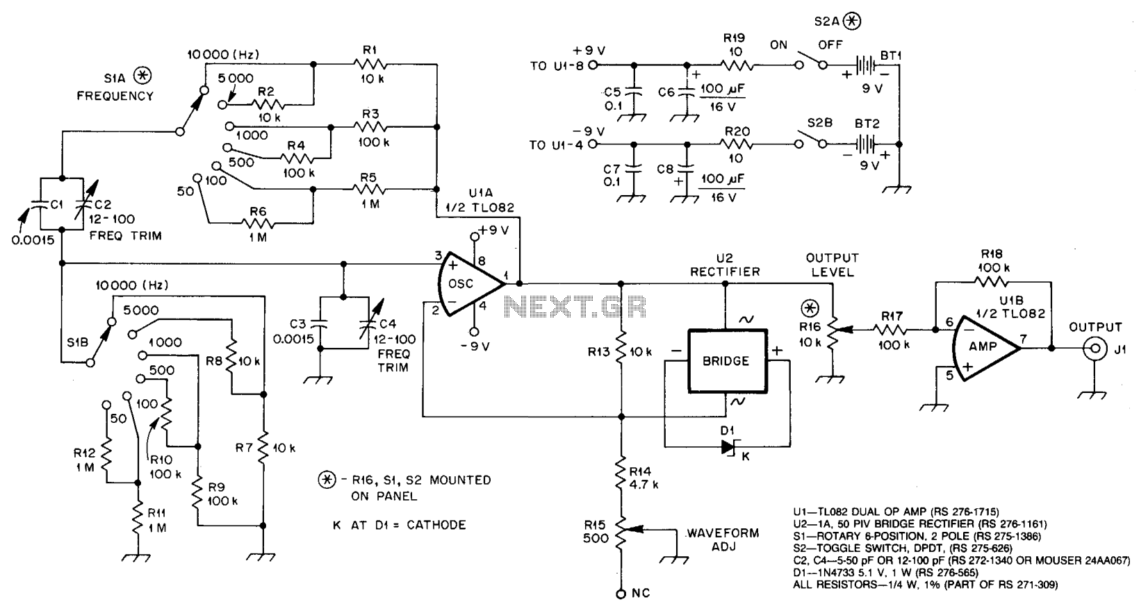
U1A, an operational amplifier, oscillates at the frequency where the phase shift in the Wien bridge network is precisely zero degrees. Adjusting the component values of the bridge alters the oscillator frequency. In this circuit, only the two resistors...
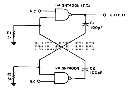
With the values shown, the circuit generates a 2-MHz symmetrical square wave. Changing capacitors C1 and C2 to 0.01 µF results in a frequency of 500 Hz. For the particular integrated circuits and power supply voltages (5.0 V), the...
A useful feature of this circuit is that the frequency can be changed by modifying the capacitor value. A switch can be added to select between various frequencies. This circuit utilizes a capacitor in conjunction with an oscillator to determine...
Here is an updated schematic featuring the RF Solutions receiver along with several minor additions. The design includes additional circuitry to manage the signals effectively. The updated schematic incorporates an RF Solutions receiver, which is essential for receiving radio frequency...

This circuit is a simple telephone ringtone generator designed using minimal components. It produces a simulated telephone ringing tone and operates on a DC voltage ranging from 4.5V to 12V. This circuit can be utilized in standard intercom systems...