
5A H-Bridge Module Pinout Circuit Schematic for Bipolar DC Motor
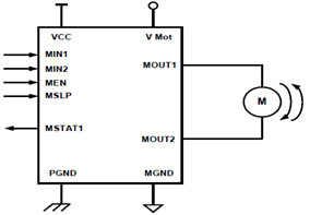
The 5A H-Bridge Module serves as a critical component in controlling the direction and speed of a Bipolar DC motor. It allows for bidirectional control of the motor by enabling the flow of current in either direction through the motor windings. The H-Bridge configuration typically consists of four switches (transistors or MOSFETs) arranged in an "H" pattern, which facilitates the reversal of current flow.
The J1 connector terminal set is used for power supply and motor connections, while the J2 header set provides an interface for control signals. The J2 pinout typically includes pins for PWM (Pulse Width Modulation) control, direction control, and ground connections. The PWM signal modulates the effective voltage supplied to the motor, allowing for speed control, while the direction control pin determines the rotation direction of the motor.
In practical applications, the H-Bridge Module can be interfaced with microcontrollers or other control circuits to achieve precise motor control. Proper heat dissipation measures, such as heat sinks or fans, may be necessary to prevent overheating during operation, especially under high load conditions. Additionally, the module may include features such as overcurrent protection and thermal shutdown to enhance reliability and safety during motor operation.The schematic herein appears a 5A H-Bridge Module for the working of one Bipolar DC motor. H-Bridge Module consists of one set header (J2) and one set connector terminal (J1). And here are the J2 pinout description of H-Bridge module interface:. 🔗 External reference
Related Circuits
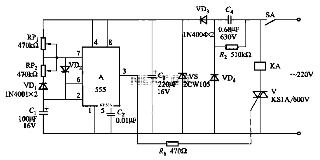
An automatic cycle switch circuit utilizing a 555 integrated circuit (IC) as the control element. It incorporates a capacitive step-down circuit and employs a bidirectional thyristor to control relays or loads with specific on and off timing. The circuit...
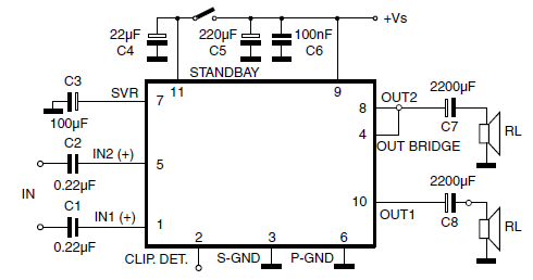
The car radio application utilizes a Class AB Audio Power Amplifier, typically featuring the TDA7360 IC. This amplifier provides 22W output in either bridge or stereo configuration and includes several beneficial features such as a minimal requirement for external...
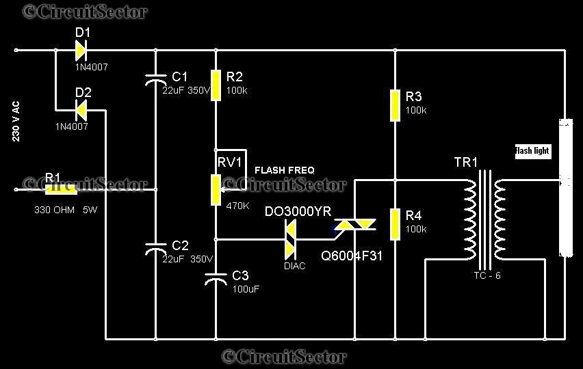
This circuit is a strobe light that allows for adjustable flashing rates. It utilizes a flash tube commonly found in cameras. In standard cameras, the flash may take ten to twenty seconds to recharge. However, this circuit enables the...
The thermocouple cold junction compensation circuit and the MAX6675 converter circuit diagram form a temperature measuring system. The system utilizes a K-type thermocouple connected to the T terminals of the MAX6675, with the cold junction grounded. An 8051 microcontroller...
Transistors are configured as a Darlington pair in this circuit. A thermistor is utilized to detect or sense heat. A 12K variable resistor is employed to adjust the activation of the buzzer at the desired temperature. The operation of...
The simplest of all motor controllers (besides a straight on/off switch) is the contactor controller. I designed this contactor controller for use in my electric scooter project. It is based around three 12V relays, two 12V batteries, two switches...