
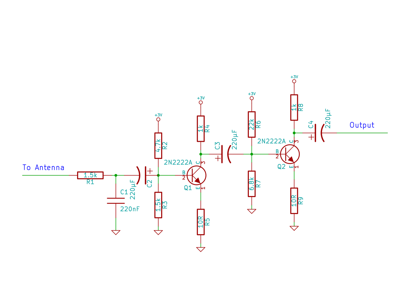
High Gain JFET Audio Amplifier
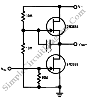
The JFET (Junction Field Effect Transistor) audio amplifier circuit is designed to amplify audio signals while maintaining low power consumption. The circuit typically consists of a JFET transistor configured in common source mode, which is known for its high voltage gain characteristics. The input signal is applied to the gate terminal of the JFET, and the output is taken from the drain terminal.
In this configuration, the JFET operates by controlling the flow of current between the source and drain terminals based on the voltage applied to the gate. The gate is reverse-biased, which allows for high input impedance and minimal loading on the preceding stage of the audio signal source. This feature is particularly advantageous in audio applications, as it preserves the integrity of the original signal.
The circuit also includes biasing resistors connected to the gate and drain to establish the proper operating point for the JFET, ensuring that it remains in the active region during operation. Capacitors may be used for coupling the input and output signals, blocking any DC components while allowing AC signals to pass through.
Furthermore, the design can be enhanced by incorporating feedback mechanisms to stabilize the gain and improve linearity. By adjusting the values of the resistors and capacitors, the gain can be tailored to meet specific application requirements.
Overall, this simple high-gain JFET audio amplifier circuit is suitable for various audio applications, including microphones, musical instruments, and other low-level audio sources, providing an efficient solution for signal amplification.This is a simple high gain JFET audio amplifier circuit. This circuit need very low power but it provides high gain amplifying function. It also called `JFET.. 🔗 External reference
Related Circuits
This compact device serves as a replacement for the input transistors and related circuitry on a single TO-220 style package. A decision was made to substitute the original driver board with a newly fabricated printed circuit board (PCB) designed...
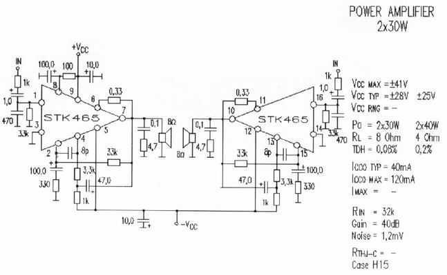
Completed STK465 is an amplifier of acoustic frequencies that offers qualitative output, using minimal exterior elements. Substantially he is one of big completed force. Has a line pins and incorporated metal surface for adaptation in cooler. The provision pins...
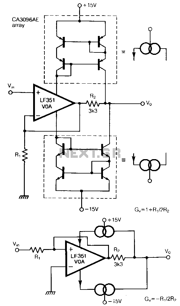
The traditional restriction of constant gain-bandwidth products for a voltage amplifier can be overcome by employing feedback around a current amplifier. Two current mirrors, constructed from transistors in a CA3096AE array, effectively turn the LF351 operational amplifier into a...
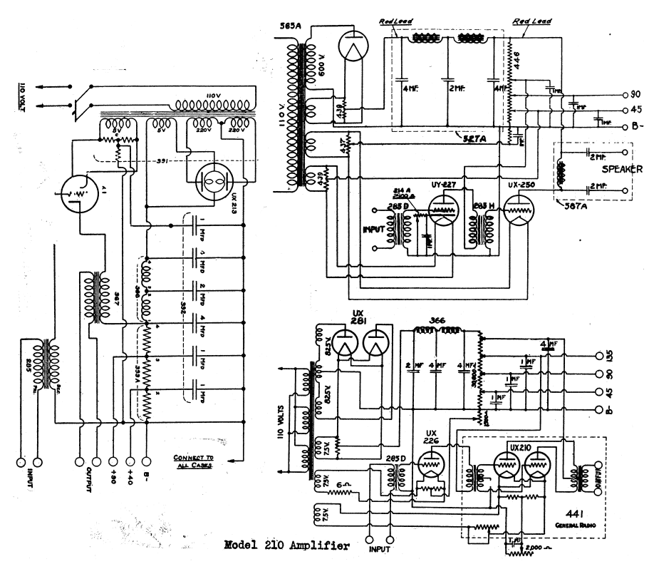
The schematic shows a valve / tube audio power amplifier and a type 390 Rectron B eliminator. The presented schematic illustrates a valve or tube audio power amplifier, which utilizes vacuum tubes to amplify audio signals. This type of amplifier...
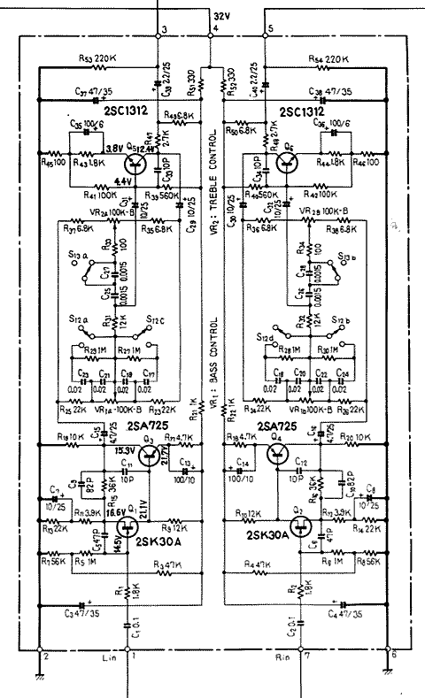
A program is needed to set the channels to their maximum level or to write the full scale to the Digital-to-Analog Converter (DAC). The MD schematics indicate that the audio signals are mixed with ratios of 0.0431 for the...
This circuit does not function as effectively as it could. It was created when the designer had a limited understanding of circuit design. An improved schematic will be developed and posted later, featuring a better design. The schematic indicates...
Warning: include(partials/cookie-banner.php): Failed to open stream: Permission denied in /var/www/html/nextgr/view-circuit.php on line 713
Warning: include(): Failed opening 'partials/cookie-banner.php' for inclusion (include_path='.:/usr/share/php') in /var/www/html/nextgr/view-circuit.php on line 713