
Old Valve Amplifier
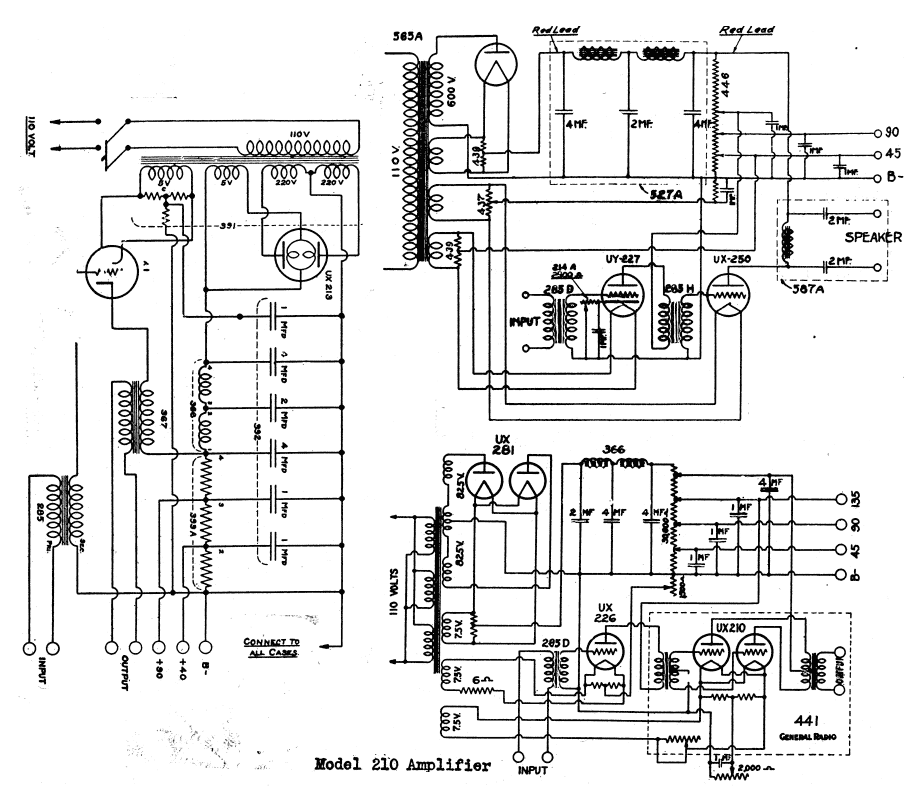
The presented schematic illustrates a valve or tube audio power amplifier, which utilizes vacuum tubes to amplify audio signals. This type of amplifier is known for its warm sound characteristics and is often favored by audiophiles and musicians for its unique tonal qualities. The amplifier typically consists of several stages, including a preamplifier stage, phase splitter, and output stage, each responsible for progressively increasing the audio signal's power.
In the preamplifier stage, low-level audio signals are applied to the input of the first vacuum tube, where they are amplified to a higher voltage level. This stage may incorporate components such as resistors, capacitors, and transformers to shape the frequency response and manage signal integrity. Following this, the phase splitter stage ensures that the signal is split into two equal but opposite phases, which is crucial for driving the push-pull output stage effectively.
The output stage, often featuring a pair of output tubes, amplifies the signal to a level suitable for driving loudspeakers. This stage may include output transformers to match the impedance of the tubes to the speakers, ensuring optimal power transfer and minimal distortion.
Additionally, the schematic includes a type 390 Rectron B eliminator, which serves as a power supply component. This eliminator converts AC voltage from the mains supply into the DC voltage necessary for the operation of the vacuum tubes. It typically consists of a rectifier, filter capacitors, and voltage regulation components to provide stable and clean power to the amplifier circuit.
Overall, the combination of the valve audio power amplifier and the Rectron B eliminator in the schematic represents a classic approach to audio amplification, emphasizing both the aesthetic and functional aspects of tube technology in sound reproduction.The schematic shows a valve / tube audio power amplifier and a type 390 Rectron B eliminator. 🔗 External reference
Related Circuits
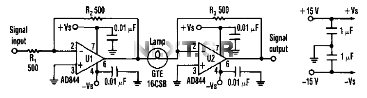
Designers can construct a 15-dB compressor using a miniature lamp and a current-feedback amplifier. The circuit exhibits extremely low distortion at frequencies above the lamp's thermal time constant, indicating that distortion remains negligible from audio frequencies to over 10...
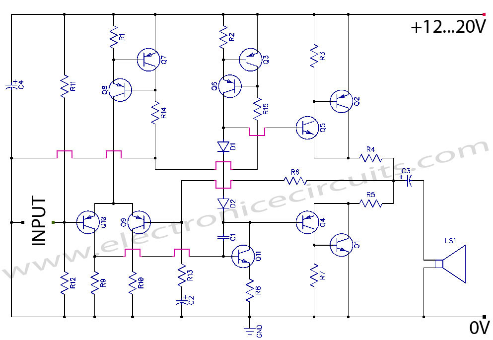
Discrete Class AB Transistor Audio Power Amplifier Circuit Diagram. This is a Class AB transistor power amplifier. It is a simple amplifier to... A Class AB transistor audio power amplifier is designed to provide high-quality amplification for audio signals while...
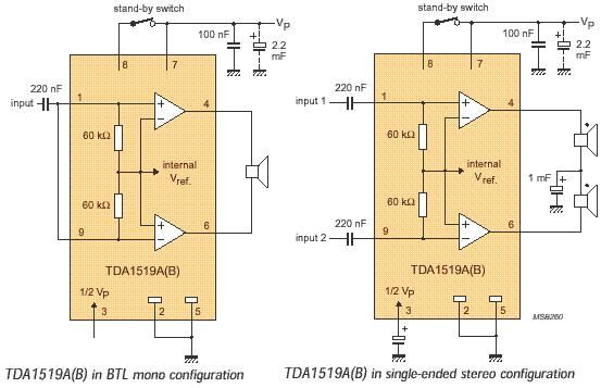
The audio amplifier circuit is based on the TDA1519 amplifier IC, which is designed for audio applications. The TDA1519 has a power output range of 2 to 6 watts. This amplifier is a Class B dual-output type and comes...
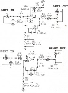
Preamplifiers are utilized to amplify low-level signals, such as those from microphones and tape heads, before they are sent to power amplifiers. Power amplifiers typically exhibit lower sensitivity. The frequency response can also be adjusted and optimized at the...
In terms of AC signals, the base is connected to the ground through capacitor C3. Consequently, both the input and output are linked to the base, forming a common base amplifier configuration. The common base amplifier is a type of...
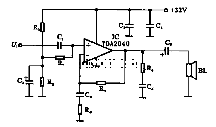
An integrated power amplifier TDA2040 is used in an OTL (Output Transformer-Less) power amplifier circuit, which operates with a +3V single supply as the working voltage. This circuit has a voltage gain of 30 dB (approximately 32 times magnification),...
Warning: include(partials/cookie-banner.php): Failed to open stream: Permission denied in /var/www/html/nextgr/view-circuit.php on line 713
Warning: include(): Failed opening 'partials/cookie-banner.php' for inclusion (include_path='.:/usr/share/php') in /var/www/html/nextgr/view-circuit.php on line 713