
High Impedance Voltmeter LM358
This circuit utilizes a high-impedance buffer configuration to mitigate the loading effect of the voltmeter on high-resistance circuits. The primary component of this design is an operational amplifier (op-amp) configured as a voltage follower. The op-amp has a very high input impedance, typically in the range of megaohms, which allows it to measure voltage without significantly affecting the circuit being tested.
In this configuration, the input of the op-amp is connected to the point in the circuit where voltage measurement is desired. The output of the op-amp is then connected to the multimeter for voltage reading. This design ensures that the input impedance of the measuring device does not load the circuit under test, allowing for accurate voltage readings even in high-resistance scenarios.
The power supply for the op-amp can be derived from a dual power supply or a single supply with appropriate biasing to ensure that the output voltage remains within the operating range of the multimeter. Additionally, decoupling capacitors should be placed close to the power supply pins of the op-amp to minimize noise and improve stability.
To further enhance the performance of the circuit, a resistor can be placed in series with the output of the op-amp to limit current and protect the multimeter from potential over-voltage conditions. It is also advisable to include a protection diode at the input stage to prevent any negative voltages from damaging the op-amp.
This high-impedance voltmeter circuit is particularly useful in applications such as testing sensor outputs, measuring voltages in high-impedance environments, and when working with delicate electronic components that may be sensitive to loading effects. Overall, this design provides a cost-effective solution for accurate voltage measurements in high-resistance circuits.This circuit is designed to provide an inexpensive way to to create a High Impedance Voltmeter while making use of an inexpensive analog or digital multimeter. When measuring voltages in high resistance circuits the resistance of the voltmeter itself has an effect on the circuit.
For example if the voltage across a 1 megohm resistor is measured with a voltmeter that has an internal resistance of 1 megohm then the total resistance in that part of the circuit is effectively halved (two 1 M resistors in parallel = 500K ohms). In another example; If a voltmeter with a 1 megohm resistance is placed in series with a 1 megohm resistance there will in effect be two - 1 megohm resistances in series, the resistor in the circuit and the resistance of the voltmeter. Under these conditi 🔗 External reference
Related Circuits
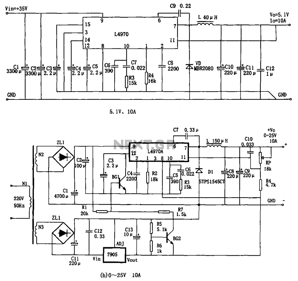
The L4970A power switching supply is a high-power monolithic integrated switching regulator, packaged in a SIP-15 format. It has specific characteristics: (1) The input voltage must be at least 11V, typically ranging from 15V to 40V; (2) The output...
The AD8205 can be utilized to create a high-side current sensing circuit with a low-side switch. In this configuration, an inductive load (such as a solenoid) and a resistive shunt are incorporated. The resistive shunt is positioned on the...
This is a simple NiCd battery charger powered by solar cells. A solar cell panel or an array of solar cells can charge a battery at more than 80% efficiency. The described circuit functions as a basic NiCd battery charger...
Precision high voltage regulator power supply. Refer to the corresponding page for an explanation of the related circuit diagram for the power supply. This simple switching regulator circuit provides a 5 V output, with the input supplied by a...
To measure the input impedance of an unknown circuit, first set the signal generator to a current source with a magnitude of 1 amp. A shunt resistor of 100 megohms is also required. This setup is beneficial for measuring...
The UBA2021 can be utilized as a 600 V lamp controller and half-bridge driver integrated circuit (IC) for high-power applications. It is designed for long-life compact fluorescent lamp (CFL) and tubular fluorescent lamp (TL) applications. The UBA2021 is a versatile...