
Measuring Impedance with Circuit Maker
To accurately measure the input impedance of an unknown circuit, the initial configuration involves utilizing a signal generator set as a current source, specifically adjusted to deliver 1 amp. The inclusion of a 100 megohm shunt resistor is critical; it serves to prevent simulation errors that arise due to the infinite output impedance characteristic of a current source in simulation software such as Circuit Maker. This configuration is particularly effective for analyzing amplifiers, filters, and oscillator circuits.
The process begins with an AC frequency analysis, where the frequency range is established by setting a start limit at 1 Hz, while the end limit can be adjusted based on the specific circuit requirements, with 1 MHz being a common choice for audio applications. By maintaining the input at 1 amp, the y-axis of the resultant graph will directly represent the input impedance of the circuit under test. The use of Cursor B allows for precise readings at various points across the frequency spectrum, enhancing the accuracy of the analysis.
As frequency decreases, the input impedance is observed to rise, primarily due to the influence of a 1 µF input capacitor, ultimately reaching an infinite impedance at DC or 0 Hz. This behavior is essential for understanding the frequency response of the circuit.
For output impedance measurements, the signal generator is similarly configured to 1 amp and connected to the output terminals of the circuit. Given the presence of a 10 kΩ load resistor, the necessity for a high-value parallel shunt resistance is negated. As the AC frequency analysis is conducted, the output voltage across the frequency spectrum is recorded, allowing for the application of Ohm's Law to derive the output impedance. Specifically, with a fixed current of 1 amp, the output waveform directly correlates to the circuit's output impedance in ohms.
This methodology provides a rapid and effective means of evaluating both input and output impedance, enhancing the understanding of circuit behavior across varying frequencies. Notably, the compatibility of these measurements with all versions of Circuit Maker ensures broad applicability in electronic circuit analysis.To measure the input impedance of an unknown circuit first set the signal genaerator to a current source of magnitude 1 amp. You also need a shunt resistor of 100 Meg. This setup is useful for measuring amplifiers, filter and oscillator circuits. Use the signal generator as below: Now perform an AC frequency analysis. Set the start limit to 1 Hz, set the end limit to your choice. Depending on your circuit, 1MHz may be OK for audio work, though you can set any start and end limits for filter circuits. As the input is now 1 amp, the y-axis now directly reads the input impedance of your circuit. Cursor B can be scrolled across the spectrum, see example below: The cursors allow easier reading intermediate points.
The input impedance increases at low frequencies due to the 1u input capacitor. The impedance would be infinite at DC or 0Hz. The 100M shunt resistor across the generator is necessary as the output impedance of a current source in circuit maker is infinite, omitting this resistor will result in a simulation error. A similar method is used for measuring output impedance. The signal generator is again set to a current source of magnitude 1 amp. The generator will be applied to the output circuits terminals, as shown below. In this circuit, the output has a 10 k load resistor so a high value parallel shunt resistance is superfluous.
When an AC frequency analysis is performed, the graph reads the output voltage across the frequency range. From ohms law V = I x R. As I is set at 1 amp, then the output waveform is now a direct measurement in ohms of the circuits output impedance.
Results are shown below: This is a quick method and an alternative to measuring output voltage divided by circuit output current. Both input and output impedance measurements should be compatible with all versions of circuit maker.
🔗 External reference
Related Circuits
A MOSFET is employed to drive a load that includes a sense resistor in its current path. The voltage across this resistor is utilized to trigger a circuit capable of disconnecting the load in the event of an overcurrent...
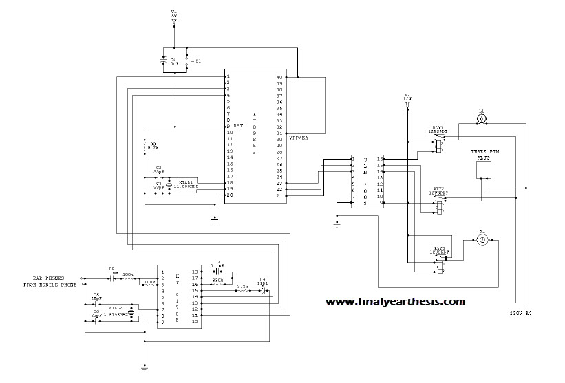
The objective of the project is to create a system that utilizes mobile technology to manage various home appliances based on signals sent from a mobile device. This innovative concept allows for the remote control of appliances through GSM...
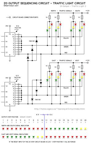
The current application involves the use of the VHDL hardware description language for designing a traffic light system controller circuit. This design is implemented within the Altera MAX PLUS EDA software environment, which facilitates compilation, simulation, and programming for...
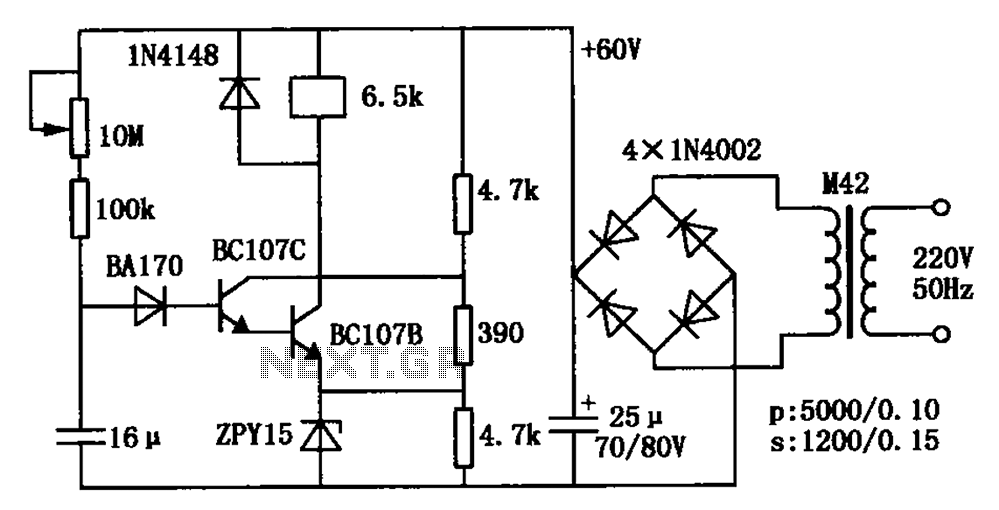
The circuit is a relay delay pull transistor configuration. Initially, when powered, the 16 µF capacitor has a voltage of zero, resulting in both transistors being off, and the relay remains inactive. As the 16 µF capacitor charges over...
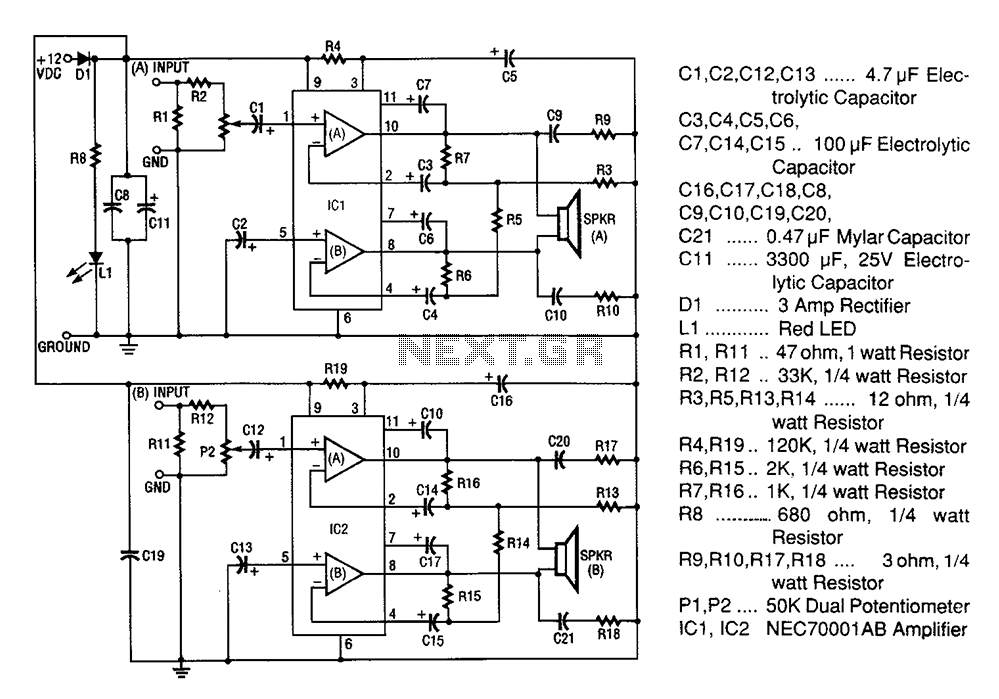
A 20W + 20W stereo amplifier comprises two independent 20-watt RMS amplifiers configured in a bridge arrangement. The input source is connected to a shunt voltage amplifier through resistors R1, R2, and potentiometer P1. Resistor R1 provides load resistance...
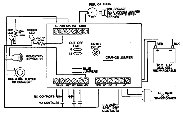
The following alarm circuit is designed with features that may be suitable for residential and commercial alarm system applications. It has a 12V and 1.5A regulated power supply. Furthermore, this residential alarm circuit also includes a delay circuit, a...
Warning: include(partials/cookie-banner.php): Failed to open stream: Permission denied in /var/www/html/nextgr/view-circuit.php on line 713
Warning: include(): Failed opening 'partials/cookie-banner.php' for inclusion (include_path='.:/usr/share/php') in /var/www/html/nextgr/view-circuit.php on line 713