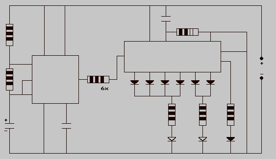
High-intensity LED Warning Flasher

This circuit was designed as a warning flasher to alert road users to dangerous situations in the dark. Alternatively, it can act as a bicycle light.
The circuit operates by utilizing a light-emitting diode (LED) as the primary visual alerting component. The design typically includes a microcontroller or a timer integrated circuit (IC) to control the flashing pattern of the LED. The microcontroller is programmed to turn the LED on and off at specific intervals, creating a flashing effect that is highly visible in low-light conditions.
Power for the circuit can be supplied by a battery, ensuring portability and ease of use. The circuit may also include a switch to turn the device on and off, allowing users to activate the warning flasher only when necessary. Additionally, resistors are included in the circuit to limit the current flowing through the LED, preventing damage and ensuring optimal brightness.
For bicycle use, the circuit may be encased in a waterproof housing to protect the components from environmental factors. The design may also incorporate mounting brackets or clips to securely attach the light to the bicycle frame.
Overall, this circuit serves a dual purpose: providing a safety warning to road users and enhancing visibility for cyclists. Its simple yet effective design makes it a valuable tool for improving safety in dark conditions.This circuit was designed as a warning flasher to alert road users to dangerous situations in the dark. Alternatively, it can act as a bicycle light (subj.. 🔗 External reference


