
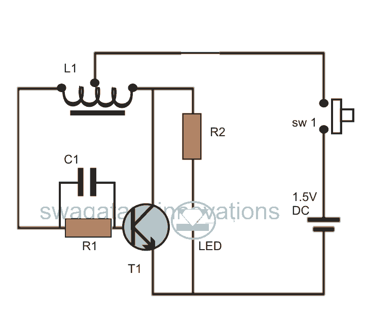
Phone Line In use LED

The described circuit functions as a telephone line indicator, specifically designed to detect when a telephone handset is lifted off the hook. It is connected in parallel with the telephone line, allowing it to monitor the line voltage. The circuit utilizes a bridge rectifier formed by diodes D1 through D4, which safeguards the circuit against incorrect polarity connections that may occur when interfacing with the telephone line.
In normal operation, when no telephone is lifted, the line voltage remains between 50V and 70V. This voltage is applied through the bridge rectifier and is processed by resistors R1 and R2, which bias the gate of the field-effect transistor (FET) Q1, keeping it in the off state. When a telephone handset is lifted, the line voltage drops significantly, which allows Q1 to turn on. This action energizes the red LED (D6), providing a visual indication that a telephone is in use.
The circuit includes a current-limiting resistor (R3) that restricts the current flowing through the LED to a maximum of 10mA, preventing damage to the LED. A Zener diode (D5) is incorporated to clamp the gate voltage of Q1, ensuring it does not exceed 10V, which protects the FET from over-voltage conditions. Capacitor C1 serves as a filter, smoothing out any parasitic pulses that may be present on the line, thereby enhancing the stability of the circuit.
For optimal performance, if issues with circuit adaptation or operation arise, it may be necessary to replace R1 with a higher resistance value, up to 220kΩ. Similarly, R3 can be omitted if the circuit operates correctly without it. The circuit is designed to function with a supply voltage ranging from +3V to +9V, typically provided by a battery, and has a low current consumption, making it suitable for prolonged use.
The part list includes:
- R1 = 1 MΩ
- R2 = 100 kΩ (as per text)
- R3 = 47 Ω
- C1 = 1 µF, 63V
- D1, D2, D3, D4 = 1N4001 (Rectifier Diodes)
- Q1 = BF256B (Field-Effect Transistor)
- D5 = 10V, 1W Zener Diode
- D6 = Red LED
- B1 = Battery with voltage range of 3V to 9V.If we have a lot of parallel telephones on a telephone line, we needed a unit that will have the possibility of showing if somebody of the telephone has raised the earphone. Our this possibility give the circuit. The circuit is connected at parallel with the two cables of telephone line. The bridge of rectification D1- D4, protect and ensure the circuit from error polarity connection. If no telephone is not raised, then voltage in telephone is 50V until 70V roughly. This voltage via the bridge and resistors R1-2 turn on the gate of Fet Q1, in order that this not open.
As soon as is raised a telephone then the voltage in line fall, Q1 turn on and the D6 it lighten, showing the situation of line. Because of the Q1 and R3 the current that leak Led D6 it is limited in 10mA. The diode zener D5 prevent the voltage of gate of Q1, to pass above 10V, while capacitor C1 function as filter for parasitic pulses. If they exist problems of adaptation and operation of circuit should is replaced the R1 with other of bigger price (until 220K).
The himself is also in effect for R3, who can be suppressed, if the circuit work and without the R3. The circuit function with supply + 3V until + 9V, from battery, one and the consumption is enough small. Part List R1=1Mohms C1=1uF 63V D6=Led RED R2=100Kohms see text D1-2-3-4=1N4001 Q1=BF256B R3=47 ohms D5=10V 1W Zener B1=3V.....9V Battery
🔗 External reference
Related Circuits
This post discusses blue and white LED drivers utilizing a joule thief circuit. Further exploration of the circuit's functionality is provided, along with simulation points. The joule thief circuit is a simple and efficient boost converter that allows for the...
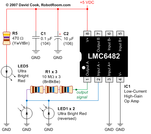
This circuit converts the analog signal from the reversed LED, which is in sensing mode, and amplified by the operational amplifier, into a digital (on/off) signal. The original complex design has been simplified. An alternative approach is discussed in...
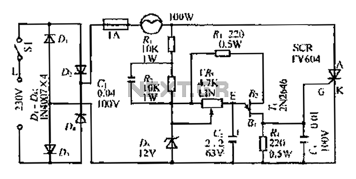
An AC voltage of 30V is rectified. The positive terminal is connected to a fuse and a 100W bulb, while the negative terminal is connected to a thyristor. A Zener diode provides a stable bias voltage. A variable resistor...
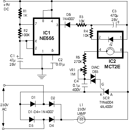
This circuit can be used to construct an attractive Christmas Star. When we switch on this circuit, the brightness of lamp L1 gradually increases. When it reaches the maximum brightness level, the brightness starts decreasing gradually. And when it...
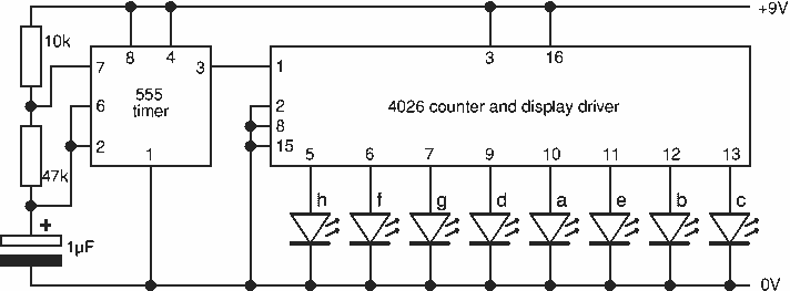
This project flashes eight LEDs in an apparently random manner. It uses a 4060 combined counter and display driver IC which is designed for driving 7-segment LED displays. The sequence is not really random because seven of the LEDs...
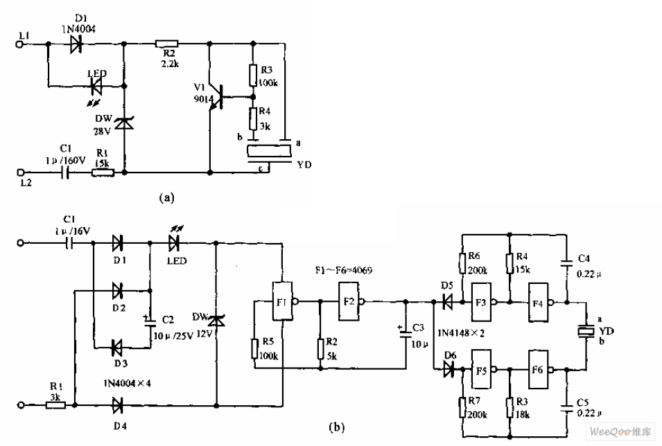
The telephone electronic ringer circuit is illustrated in the provided figure. It features an NPN transistor (either 9014 or 3DG12) as the primary component. The sound device, referred to as YD, functions as both a feedback device and is...