
High/Low Voltage Probe
The simple voltage probe circuit serves as an essential tool for engineers and technicians engaged in the testing and troubleshooting of electronic components. The design typically consists of a high-impedance voltage divider configuration, which allows for accurate measurement of voltage levels without significantly loading the circuit under test.
The circuit is generally composed of two resistors, R1 and R2, connected in series. The input voltage is applied across the series combination, while the output voltage is taken from the junction between R1 and R2. The values of R1 and R2 are chosen based on the desired input voltage range and the expected output impedance. This configuration ensures that the probe can measure voltages across a wide range of circuits, from low-voltage digital circuits to higher voltage analog circuits.
In addition to resistors, the circuit may incorporate a capacitor for AC coupling, allowing the probe to measure AC signals without the influence of DC bias levels. Furthermore, an operational amplifier can be integrated into the design to buffer the output, providing a low-output impedance while maintaining high input impedance. This buffering is crucial for ensuring that the probe does not affect the circuit being tested.
The voltage probe circuit can also be equipped with an LED indicator to provide a visual representation of the voltage being measured. This feature can enhance usability during testing, especially in low-light conditions or when monitoring multiple points simultaneously.
Overall, the simple voltage probe circuit is an invaluable instrument in electronic testing, providing reliable and accurate voltage measurements while minimizing the impact on the circuit under observation.Simple voltage probe circuit shown in the schematic diagram below very useful in testing, testing, or troubleshooting discrete or integrated circuits,.. 🔗 External reference
Related Circuits

The term VCXO refers to a Voltage Controlled Crystal Oscillator. The frequency of this oscillator can be fine-tuned by varying the control voltage. VCXO clock generators are utilized in a range of applications, including digital telecommunications. VCXO circuits are essential...
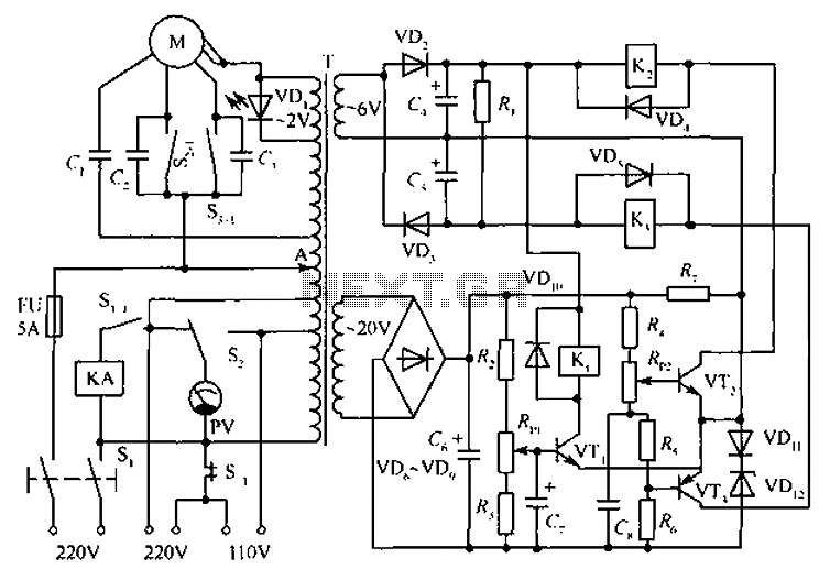
The circuit depicted in the figure includes an automatic voltage regulator (T) that maintains a constant output by utilizing a servo motor. The circuit features transistors VT1 and VT2 (3DK9), with a capacitance range of C (65 ~ 85)....

This voltage booster circuit for driving one or more white LEDs utilizes a 555 timer as its main component. The timer, designated as IC1, operates as a resettable astable multivibrator with R1, R2, and C2 serving as the timing...
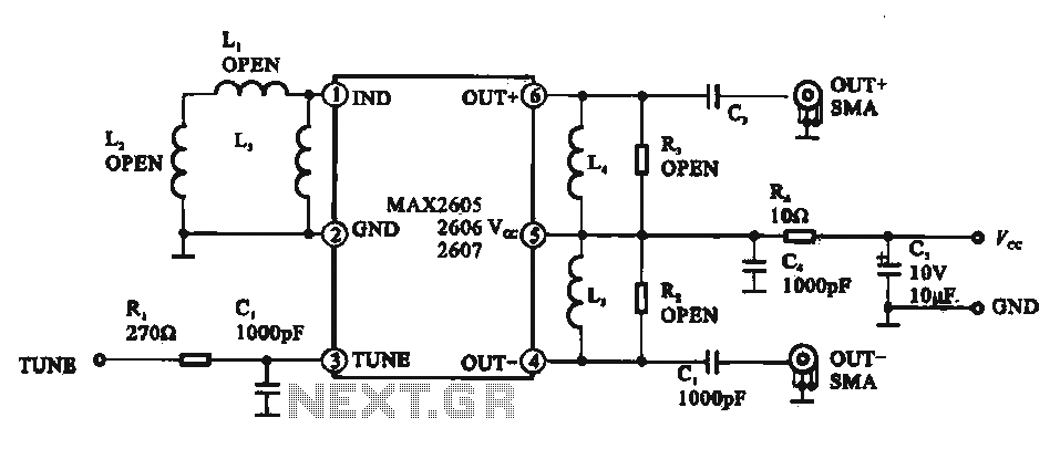
A low phase noise voltage-controlled oscillator circuit is presented, specifically integrated within the MAX2605-2609 voltage-controlled oscillator series. The circuit features a tuning voltage control terminal, allowing for adjustable oscillation frequency through a DC voltage input. The output of the...
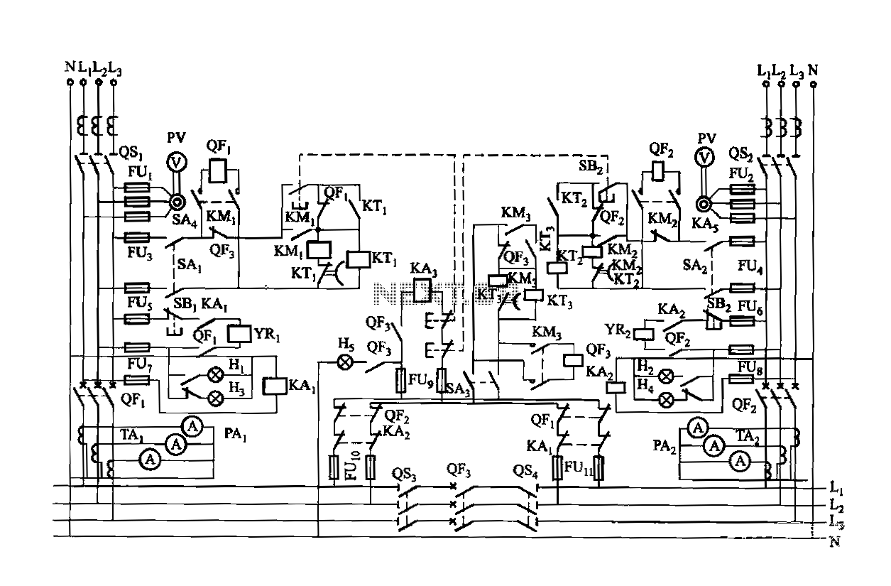
Dual power is provided for each complex, as the load is supplied through a two-way power system. In the event of a power outage, the contact switches transition from a closed position, allowing the power supply circuit to bear...
A high voltage power supply is a valuable source that can be effectively used in various applications, such as biasing gas-discharge tubes and radiation detectors. This type of power supply can also serve as a protective measure, such as...