
High- Or Low-Input Regulator
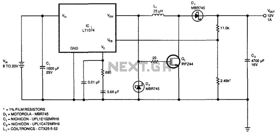
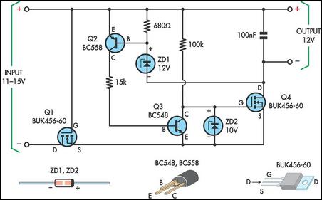
The described voltage regulator circuit is designed to deliver a stable output voltage of 12 V at a load current of 1 A, making it suitable for various applications where a reliable power supply is required. The input voltage range of 8 to 20 V provides flexibility in the choice of power sources, allowing for operation with standard power supplies and batteries.
The adjustment of the output voltage is facilitated by modifying the feedback network consisting of the resistors ll-kii and 2.49 kΩ. By selecting appropriate resistor values, the feedback voltage at the VFB pin of the integrated circuit (IC1) can be set to 2.21 V, which is critical for achieving the desired output voltage regulation. This feature allows for customization of the output voltage to meet specific application requirements.
To ensure the safe operation of the circuit when subjected to higher input voltages, it is essential to implement a gate clamping mechanism on Q1. This transistor should be protected from exceeding its maximum gate-source voltage rating of 20 V, which could otherwise lead to damage or failure of the component.
The efficiency of the regulator is a crucial parameter, particularly in battery-powered applications where power conservation is important. With an output current exceeding 0.5 A, the circuit can achieve efficiencies greater than 70%. This efficiency rating indicates that the regulator is capable of minimizing power loss during operation, thereby enhancing the overall performance of the system. Furthermore, when the input voltage exceeds 15 V, the circuit is capable of supplying more than 2 A of output current, making it suitable for more demanding applications that require higher power levels.
Overall, this voltage regulator circuit exemplifies a practical solution for providing a stable output voltage across a range of input conditions while ensuring efficiency and adaptability for various electronic applications. This regulator provides 12 V at 1 A out with an input voltage of 8 to 20 V. Output voltage can be changed by c harging the ll-kii and 2.49-KOhmhm resistors to provide 2.21 V at the VFB pin of IC1, if desired. If you need to handle a higher input voltage, make sure to clamp the gate of Ql below its 20-V max. rating. Efficiency can exceed 70% for output currents greater than 0.5 A; above 15-V input voltage, more than 2 A of output current can be obtained. 🔗 External reference
Related Circuits
This is a simple circuit of a low-power voltage regulator reference. This circuit can produce a stable voltage reference. The low-power voltage regulator reference circuit is designed to provide a consistent output voltage, which is crucial for various electronic applications...
Use one FET, one Zener diode, and one resistor. The FET and resistor are unnecessary if the current is within the specifications for the Zener diode. Alternatively, a P-channel device may be used. The described circuit configuration includes a Field...
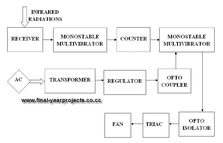
This report presents a comprehensive overview of a mini project titled "Remote Controlled Fan Regulator," developed in accordance with the curriculum requirements for the sixth semester of the Bachelor of Technology degree in Electrical and Electronics Engineering. The report...
This circuit is designed to power a laptop computer using a solar power setup. The computer requires 12V at 3.3A. The circuit employs a linear regulator with a MOSFET (Q4) as the series pass device. A 100kΩ resistor provides...
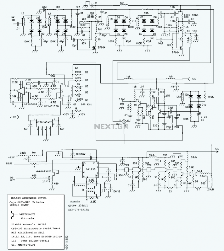
A block diagram and a schematic of the receiver are shown in Figures 2 and 3, respectively. In Figure 3, L6 and L7 are spaced 0.6 inch for a loss of about 0.5 dB. Q4 is the first RF...

This second-order filter, designed for audio applications, utilizes an LM1458 or a similar operational amplifier. It is tunable with a cutoff frequency ranging from 30 Hz to 300 Hz. The resistors R2a and R2b are ganged log-taper potentiometers. The described...