
Remote Controlled Fan Regulator EEE Project Report
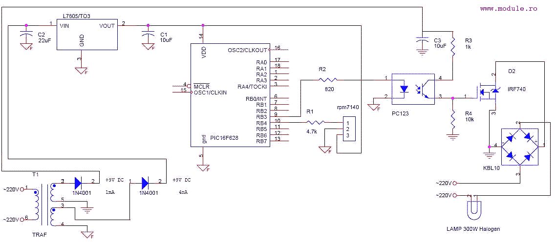
The remote-controlled fan regulator project integrates several key electronic components and principles to achieve effective fan speed control. At the heart of the system is a Triac, which acts as a semiconductor device capable of controlling power flow to the fan motor. The firing angle of the Triac is modulated through a microcontroller, which receives input signals from a remote control.
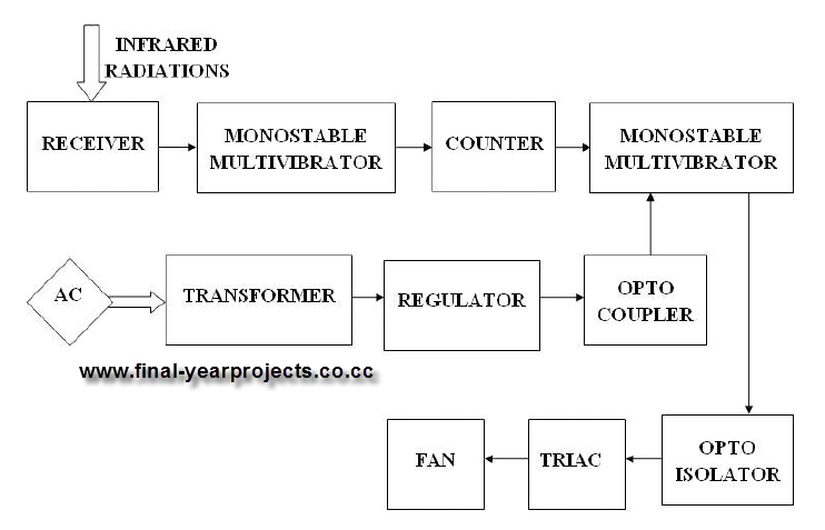
The block diagram of the system typically includes the following sections: a remote control unit, a receiver module, a microcontroller unit, a Triac driver circuit, and the fan motor. The remote control unit transmits commands that are received by the receiver module, which decodes the signals and sends the corresponding commands to the microcontroller. The microcontroller processes these commands and determines the appropriate firing angle for the Triac, effectively controlling the voltage applied to the fan motor.
The circuit diagram outlines the connections between the components, highlighting the power supply, the Triac with its gate control, and the fan motor. Protection elements such as fuses or circuit breakers may also be included to ensure safety during operation. The working principle revolves around phase control, where the Triac is triggered at specific intervals within each AC cycle, allowing for the adjustment of power delivered to the fan.
The component list for the project typically includes a microcontroller (such as an Arduino or PIC), a Triac (like the BT136), a receiver module (such as an IR receiver), resistors, capacitors, and a fan motor. Each component plays a critical role in ensuring the system operates efficiently and safely.
This project not only demonstrates the application of electronic principles but also provides a practical solution for controlling fan speed remotely, enhancing user convenience and energy efficiency.This is a good Electrical & Electronics mini project report on "Remote Controlled Fan Regulator" and submitted in accordance with the curriculum requirements for sixth semester of the degree course in Bachelor of Technology in the branch of Electrical and Electronics Engineering. This final year EEE report is divided into 15 chapters. By doing thi s project we can regulate the speed of the fan by using a remote. Here the variation in the firing angle of Triac is used for regulating the speed. You can also Subscribe to FINAL YEAR PROJECT`S by Email for more such Projects and Seminar. The above image shows the block diagram of remote controlled fan regulator which is divided into different section. This report also contains the circuit diagram, Working principle, Component list of remote controlled fan regulator.
Use this project report for your study and reference work. 🔗 External reference
Related Circuits
The timer generates a basic period (for instance, 20 ms), and with certain associated variables, it is possible to activate an I/O pin to produce a signal. By utilizing an 8-bit variable, the generated frequency can be divided into...
The remote control tester circuit is a simple and easy-to-construct device for verifying the basic operations of an infrared remote control unit. It is low-cost and designed around infrared technology. The remote control tester circuit typically consists of a photodiode...
This system uses a transmitter operating at approximately 100 kHz to control a remote receiver. A line splitter can connect the transmitter to the active telephone line. The transmitter is a CMOS oscillator equipped with output buffer stages to...
This is a simple schematic designed to control a lamp using a Sony TV remote control. The circuit employs a PWM signal connected to a photocoupler, which isolates the power section from the microcontroller. The power section features an...
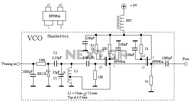
The VCO is based on a Hartley oscillator. The frequency is determined by L1 and capacitor C1. The tuning voltage will change the capacitance in the varactor BB132 which will change the oscillation frequency. The value of capacitor C2...
In 1991, there was significant interest in a specific display technology that was difficult to find locally and expensive to import. Currently, this technology has become widely available and is considered obsolete due to the affordability and accessibility of...
Warning: include(partials/cookie-banner.php): Failed to open stream: Permission denied in /var/www/html/nextgr/view-circuit.php on line 713
Warning: include(): Failed opening 'partials/cookie-banner.php' for inclusion (include_path='.:/usr/share/php') in /var/www/html/nextgr/view-circuit.php on line 713