
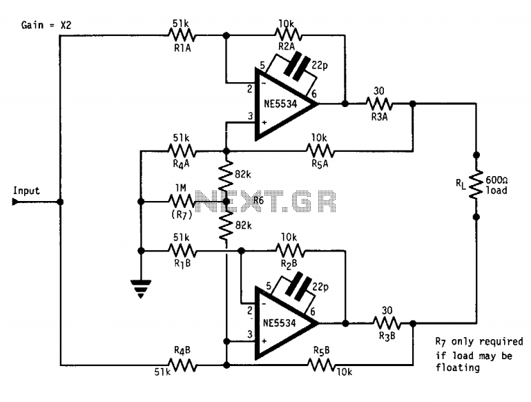
High output 600 Ohm line driver
The described circuit operates under the principle of a floating output, which is crucial in applications requiring isolation from ground potential. The push-pull configuration of the current sources allows for efficient signal handling while maintaining high output impedance. This characteristic is particularly beneficial in applications where the load may not have a stable ground reference, such as in sensor applications or in environments with varying ground potential.
The use of operational amplifiers (op-amps) in this design enhances the circuit's performance by allowing for precise control of the output characteristics. The differential output impedance can be adjusted through the addition of a resistor between the non-inverting terminals of the op-amps, which balances the circuit without compromising the common mode performance. This balance is vital for minimizing distortion and ensuring signal integrity, especially in sensitive applications.
Resistor R7 plays a critical role in adjusting the common mode impedance, which can help stabilize the circuit when the load is floating. By carefully selecting the value of R7, the common mode impedance can be fine-tuned to prevent malfunctions that may arise from floating conditions. Furthermore, maintaining close tolerances on all resistors is essential to ensure that the circuit operates as intended and provides reliable performance.
The line driver’s capability to deliver +24 dB from ±12 V or +16 dB from ±6 V supplies indicates that the circuit is designed to handle a wide range of power supply configurations, making it versatile for various applications. The output gain levels suggest that the circuit can effectively drive loads while maintaining the desired signal amplitude, which is critical in communication systems and audio applications.
Overall, this circuit design exemplifies a robust approach to achieving a floating output while ensuring high performance and reliability across various operating conditions.The circuit has a "floating" output, i.e., it behaves like an isolated transformer winding, with the output amplitude remaining unchanged whether the center or either end of the load is grounded. This is achieved by making Z-out, common mode, infinite. The circuit consists of two current-sources in push-pull. Since each has infinite output Z, the common mode output impedance is also infinite. Connecting a resistor between the non-inverting terminals of the op amps reduces the differential Z-out without affecting the Z-common-mode.
Since the output is floating, if the load is also floating there is no output ground reference, which results in malfunction. This can be corrected by reducing the common-mode slightly. R7 fulfills this function. All resistors should be of close tolerance to give a good balance. The line driver provides +24 dB from ± 12 V or +16 dB from ±6 V supplies. 🔗 External reference
Related Circuits
The voltage Vc1 increases linearly when the pull-up resistor RA in the monostable circuit is replaced with a constant current source, resulting in a linear ramp. The circuit for generating the linear ramp and the corresponding waveforms are illustrated...
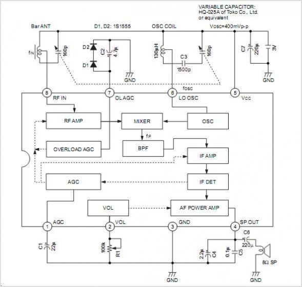
The CXA1619BM and CXA1619BS are one-chip FM/AM radio integrated circuits developed by Sony Corporation. These ICs are intended for use in radio-cassette tape recorders and headphone tape recorders, offering a variety of functions. The CXA1619BM and CXA1619BS are designed to...
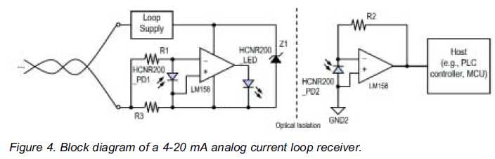
High linearity analog optocouplers offer the versatility needed to address a variety of analog isolation requirements. For high voltage applications, these optocouplers can effectively transmit analog signals between high voltage and low voltage areas without introducing distortion. This article...
Designing various electronic circuit systems (synthesizer, modem, decoder, data converter, etc.) often requires a frequency modulator subsystem. An FM modulator is a crucial component in these systems. An FM modulator is an electronic device that encodes information in a carrier...
There are neighbors who may disturb you with loud televisions or radios. A solution is available. This jammer emits jamming waves that affect the TVs and radios in the neighborhood, so caution is advised. This device is an enhanced...
The interest in tube circuits remains significant. Therefore, I will provide a comprehensive circuit of a preamplifier that is sufficiently detailed. It is primarily composed of the main preamplifier department, the input selector department, application voltage delay, and the connection...