
555 IC Linear Ramp (Sawtooth) Generator/Oscillator
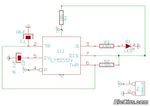
The described circuit utilizes a monostable configuration where the replacement of the pull-up resistor RA with a constant current source allows for the generation of a linear voltage ramp across the capacitor C1. This configuration is particularly useful in applications requiring precise timing and linear voltage changes. The PNP transistor serves as the active element that regulates the current flowing through the capacitor, ensuring that it remains constant.
When the timer is triggered, the PNP transistor is activated, allowing a steady current to flow through the capacitor. The relationship between the current, capacitance, and the resulting voltage across the capacitor is described by the formula V = I * t / C, where I is the constant current, t is the time duration, and C is the capacitance.
In this case, the specified parameters yield a ramp rate of 9.77V/ms, indicating that the voltage across the capacitor increases at this rate as long as the current remains constant. This behavior is critical in timing circuits, pulse generation, and signal conditioning applications where a predictable voltage change is required.
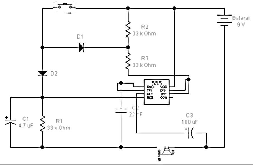
The schematic diagram referenced from Philips Semiconductors Application Notes provides a visual representation of the circuit, illustrating how the components interact to produce the desired linear ramp output. This design can be adapted for various electronic applications, including waveform generation, analog signal processing, and timing control systems, making it a versatile solution in electronic engineering.The Vc1 increases linearly when the pull-up resistor RA in the monostable circuit is replaced with constant current source, generating a linear ramp. The linear ramp generating circuit and the generated linear ramp waveforms illustration is shown in figures below.
The current flowing through capacitor C1 becomes a constant current generated by PNP transistor and resistor when the trigger starts in a timer configured as shown in figure below. In other words, we can obtained the gradient of the linear ramp function appearing across the capacitor by using the constant current flowing through the capacitor. The gradient of the ramp function at both ends of the capacitor is S = 0. 215m/0. 022 = 9. 77V/ms if the constant current flow through the capacitor is 0. 215mA and the capacitance is 0. 02uF. [Circuit`s schematic diagram source: Philips Semiconductors Application Notes] We aim to transmit more information by carrying articles.
Please send us an E-mail to wanghuali@hqew. net within 15 days if we are involved in the problems of article content, copyright or other problems. We will delete it soon. 🔗 External reference
Related Circuits
Some simple 555 and flip-flop circuits are being developed to add electronic lighting effects to modernize games. Various circuits are being collected for different game aspects, such as idle states, flipper shots, flower openings, winning shots, etc. A collection...
RF Power Amplifier 1 Watt. Jams Cellular Downlink Band: 800-950 MHz. The RF power amplifier described is designed to operate within the cellular downlink frequency range of 800 to 950 MHz, delivering an output power of 1 Watt. Such amplifiers...
All components are arranged as depicted in the sequence below. Current will flow from the source voltage to the switch. When the switch is closed, current will flow through the diode, which acts as a closed switch due to...
This is a very simple 555 timer circuit that serves as a straightforward theft deterrent, which may be just as effective. The idea is to have a flashing red LED indicate that your car is protected. This device can...
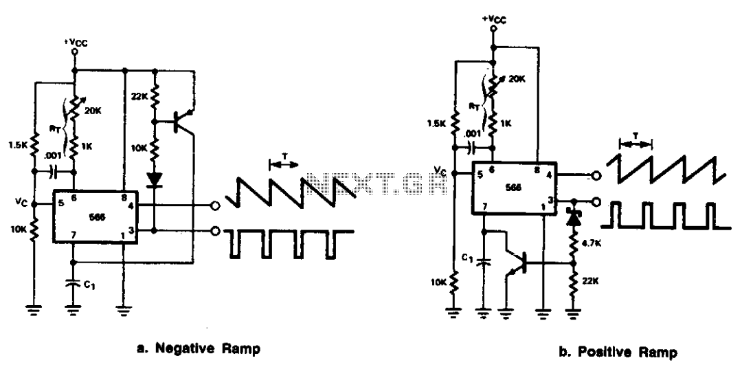
The 566 can be configured as either a positive or negative ramp generator. In the positive ramp generator configuration, the external transistor controlled by the output at Pin 3 quickly discharges capacitor C1 at the conclusion of the charging...
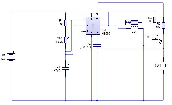
A circuit is being designed to trigger solenoid valves for airbags in a car, requiring a time range of 0 to 1 second. The selected valves operate at 12V, 0.5A, and can activate within a maximum speed of 200...
Warning: include(partials/cookie-banner.php): Failed to open stream: Permission denied in /var/www/html/nextgr/view-circuit.php on line 713
Warning: include(): Failed opening 'partials/cookie-banner.php' for inclusion (include_path='.:/usr/share/php') in /var/www/html/nextgr/view-circuit.php on line 713