
High Power AC Light Dimmer
A TRIAC-based light dimmer circuit is a common electronic design used to control the brightness of incandescent lamps and some other types of lighting. The fundamental operation of this circuit relies on the phase control technique, where the TRIAC is triggered at a specific point in the AC voltage cycle to reduce the effective power delivered to the load.
The circuit typically consists of a TRIAC, a diac or an opto-isolator, a variable resistor (potentiometer), and a capacitor. The variable resistor allows the user to adjust the phase angle at which the TRIAC is triggered. When the AC voltage reaches the set phase angle, the TRIAC turns on, allowing current to flow through the load until the voltage crosses zero, at which point the TRIAC turns off. This process repeats with each AC cycle, effectively controlling the average power delivered to the light source.
The inclusion of a diac or an opto-isolator enhances the circuit's performance by providing a more stable triggering mechanism for the TRIAC. The capacitor is used to create a delay in the triggering signal, which works in conjunction with the variable resistor to determine the phase angle.
Safety considerations must be taken into account when designing this circuit. Proper heat sinking for the TRIAC is essential to prevent overheating, and components should be rated for the expected load current and voltage.
This TRIAC-based dimmer circuit is widely used in residential and commercial lighting applications, providing an efficient and cost-effective solution for adjustable lighting control.This is a light dimmer circuit. It has no fancy special feature, it is a a quite typical TRIAC based dimmer circuit. This circuit is only used to operate with.. 🔗 External reference
Related Circuits
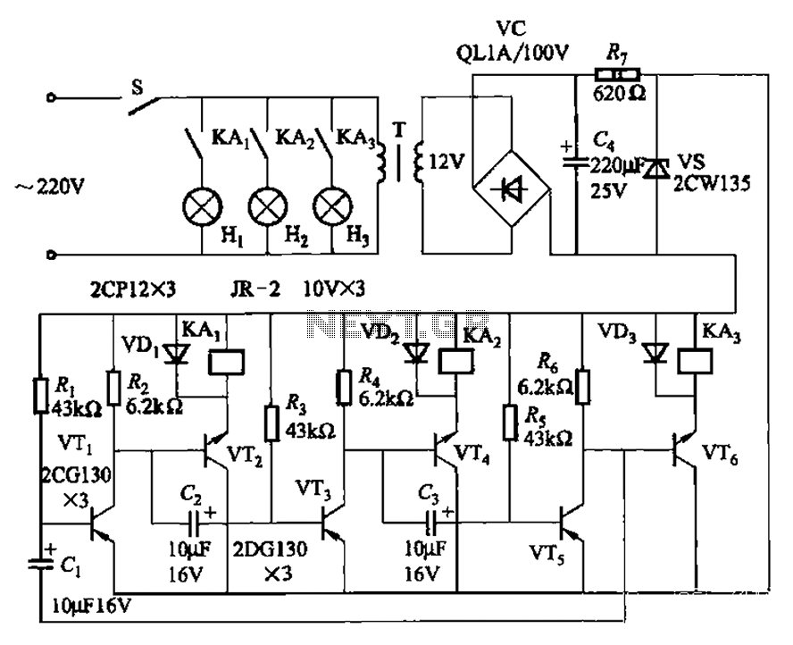
The transistors VTi, VT3, and VTs, along with the RC components, form three distinct multi-resonator oscillators. The oscillation frequency levels are dependent on the values of Ri, R3, Rs, and Cl, as well as Cz and C3s. The circuit comprises...
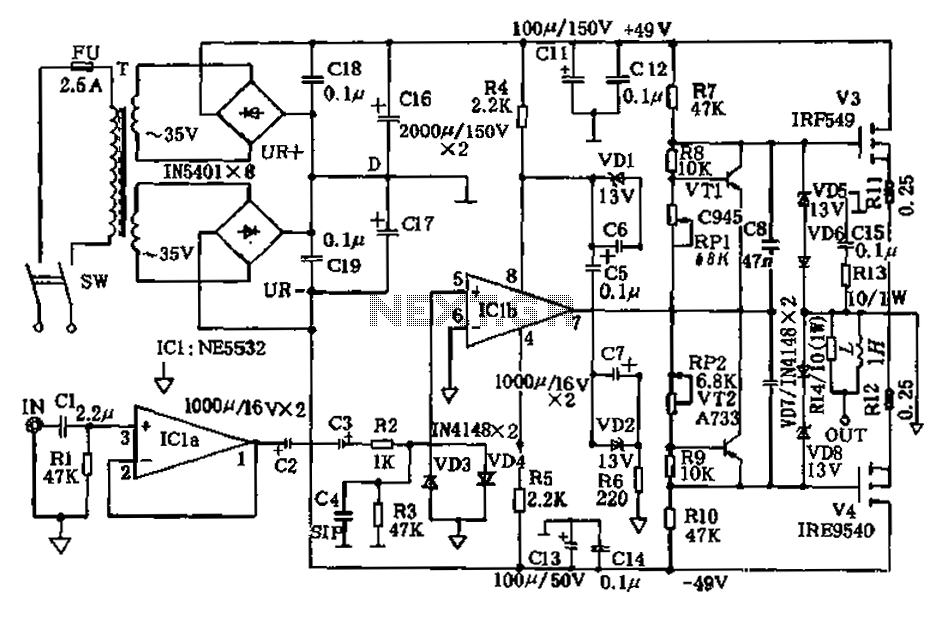
The amplifier circuit presented in this paper introduces a floating power supply aimed at increasing output power. The output power of the amplifier is influenced primarily by the final stage amplifier supply voltage. The circuit's principle is illustrated in...
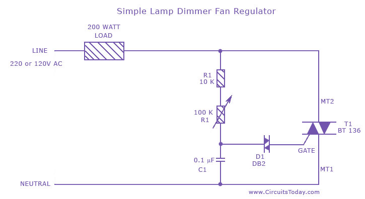
A fan regulator circuit that can also function as a simple lamp dimmer circuit. This fan speed regulator or light dimmer operates based on power control using a triac. The fan regulator circuit is designed to control the speed of...
An efficient automatic solar garden lights circuit with minimal components. The notable feature is that it operates entirely automatically, with the solar panel functioning as a light detector. The automatic solar garden lights circuit is designed to provide illumination in...
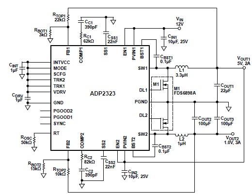
The ADP2323 DC-DC converter is designed to deliver two output voltages with specified maximum output currents. The first channel provides a 5-volt output with a maximum current of 2 Amperes, while the second channel supplies 1 volt with a...
This simple and inexpensive circuit built around a popular CMOS hex inverter IC CD4069UB offers four sequential switching outputs that may be used to control 200 LEDs (50 LEDs per channel), driven directly from mains supply. Input supply of...