
Simple Lamp Dimmer/ Fan Regulator Circuit
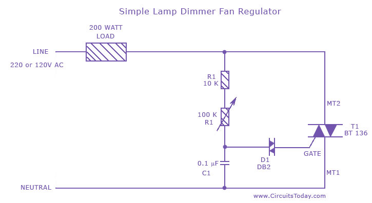
The fan regulator circuit is designed to control the speed of a fan or the brightness of a lamp by adjusting the power delivered to the load. The primary component in this circuit is a triac, which is a type of semiconductor device that can control power by switching on and off in response to a gate signal.
In operation, the triac is triggered into conduction by a gate pulse, allowing current to flow through the load. The timing of this gate pulse can be adjusted, which effectively alters the average power supplied to the fan or lamp. This is achieved through the use of a phase control technique, where the triac is turned on at a specific point in the AC waveform. By delaying the firing angle of the triac, the power delivered to the load can be reduced, resulting in lower fan speeds or dimmer light output.
The circuit typically includes additional components such as resistors, capacitors, and diodes, which work together to form a control circuit for the triac. A potentiometer may be included to allow for user adjustment of the speed or brightness. The circuit may also feature protective elements such as fuses or snubber circuits to safeguard against voltage spikes and ensure reliable operation.
Overall, this fan regulator or lamp dimmer circuit is a practical solution for applications requiring variable speed control or brightness adjustment, providing a simple yet effective means of managing electrical loads in residential or commercial settings.A fan regulator circuit which can also be used as a simple lamp dimmer circuit.This fan speed regulator or light dimmer is based on power control using triac.. 🔗 External reference
Related Circuits
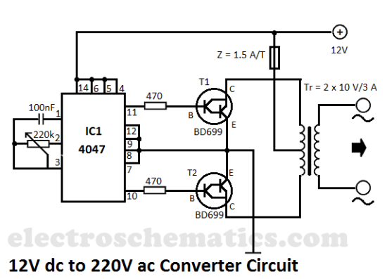
This DIY 12V to 220V voltage converter is built with a CMOS 4047, which serves as the main component of this compact voltage converter that transforms 12V DC into 220V AC. The 4047 functions as an astable multivibrator; at...
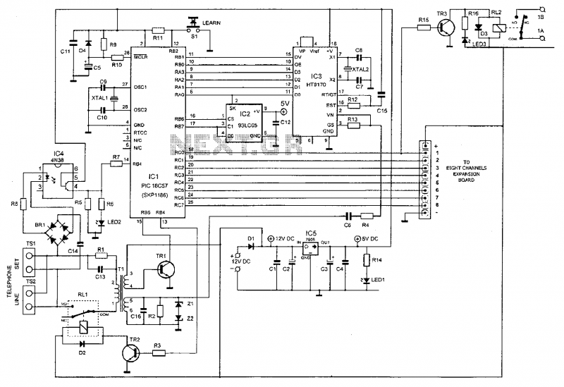
This device enables remote control of various appliances (up to eight with suitable add-on expansion boards) such as lights, water heaters, air conditioning, plant watering systems, alarms, etc., via a relay. It allows users to perform actions such as...
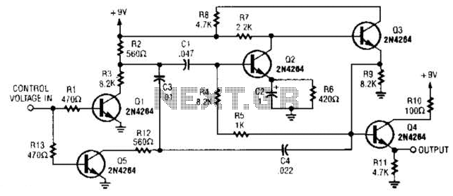
A DC control voltage varies the effective resistance in the feedback network consisting of capacitors C4, C3, C1 and resistors R12, R3. Additionally, Q2 and Q3 serve as the oscillator transistors. The circuit operates by utilizing a DC control voltage...
The thermistor utilized has a resistance of 15k ohms at 25 degrees Celsius and 45k ohms at 0 degrees Celsius. A suitable bead-type thermistor can be sourced from the Maplin catalogue. The inclusion of a 100k potentiometer enables this...
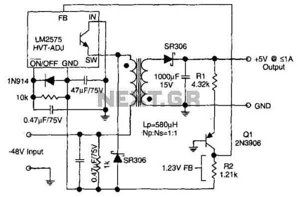
The circuit supplies 1 A at +5 V from the -48 V supply commonly used in telephone equipment. More: The National Semiconductor LM2575 is a simple switching regulator. The circuit utilizes the National Semiconductor LM2575, which is a step-down (buck)...
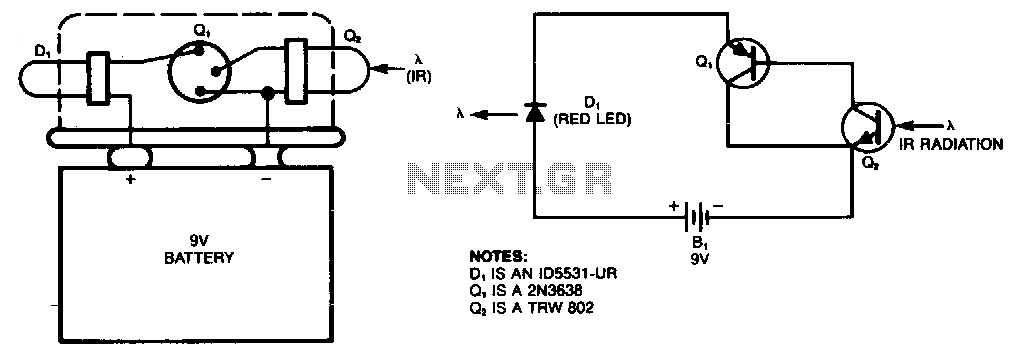
This simple infrared (IR) detector activates a red LED when the transistor Q2 is exposed to invisible IR radiation, commonly found in fiber-optic systems, position sensors, and TV remote-control units. The device can be constructed using a 9V battery...
Warning: include(partials/cookie-banner.php): Failed to open stream: Permission denied in /var/www/html/nextgr/view-circuit.php on line 713
Warning: include(): Failed opening 'partials/cookie-banner.php' for inclusion (include_path='.:/usr/share/php') in /var/www/html/nextgr/view-circuit.php on line 713