
High power bug
The FM Wireless Microphone (v5) is designed to enhance performance in terms of power output and microphone sensitivity, making it suitable for various applications, including musical instruments and remote control systems. The circuit operates with an RF amplifier buffer that provides a gain of 10dB, significantly improving transmission range and quality. The microphone sensitivity is improved through the incorporation of an audio frequency (AF) preamplifier, ensuring clear audio modulation.
The construction of the circuit is straightforward, utilizing a printed circuit board (PCB) measuring 50mm x 25mm. The inductor L1 is constructed with 3.25 turns in a spiral configuration, integral to the PCB layout, which optimizes space and performance. The circuit employs two NPN transistors, typically BC547, which can be substituted with equivalent small-signal transistors like the 2N2222. A PNP transistor, specifically the BC557, serves as the final stage amplifier.
Resistor values are critical for proper operation. A 1M0 resistor should be selected for a 5-volt DC supply at the collector of the first transistor, while a 47K resistor is appropriate for the collector of the third transistor, ensuring proper biasing and performance. Modifications to the circuit include replacing a 1n0 5mm capacitor with a 22μF electrolytic capacitor for improved stability, addressing issues of RF instability that arose with previous components.
The circuit operates efficiently, drawing approximately 30mA of current, with variations indicating proper oscillation. For dynamic microphones, it is advised to remove the 4K7 resistor to optimize performance. The output power of the circuit reaches about +10dBm, translating to a theoretical range increase of up to 1.6Km under ideal conditions, although practical testing has demonstrated effective operation at distances of around 700 meters. This design represents a significant improvement over previous versions, making it a valuable tool for both amateur and experienced electronics enthusiasts.My FM Wireless Microphone has been a very popular project with beginners and experienced constructors alike. It has been used inside guitars and as the basis of a remote control system. I do however, receive many requests for a higher powered circuit and better microphone sensitivity. Now I can introduce the new FM Wireless Microphone (v5), which also has a better frequency stability, over 1Km range (under ideal conditions) and is good on microphone sensitivity.
This has been achieved by adding an RF amplifier buffer (with 10dB gain) and an AF preamplifier to boost the modulation a little. Construction is quite simple. L1 is 3.25 turns in spiral form and is an integral part of the PCB foil pattern. The two BC547 transistors can be replaced with (almost) any small-signal NPN transistor, such as the 2N2222. The final stage is a BC557 PNP general purpose device. If you use different devices then you should select the 1M0 resistor for 5-volts DC at the collector of the the first transistor.
Select the 47K resistor for 3 - 4 volts on the collector of the third transistor. Here is the V5 component overlay drawing. Note that there is a modification: There used to be a 1n0 5mm cap for supply decoupling, but after a cange of component supplier (manufacturer?) there developed some form of RF instability when the gain of the PA transistor was a little above normal. Replacing the 1n0 to an electrolytic capacitor of 22uf cured this problem totally. Any "radial" (the leads both come out of the same end) type electrolytic capacitor from 0.47uf upwards cures the problem.
The finished unit draws about 30mA which should vary as you touch the tuned circuit, a good test that the unit is oscillating. You should remove the 4K7 resistor if you use a dynamic microphone. The PCB is 50mm x 25mm, a little larger than the first version but there are three stages instead of just the one.
The first prototype is shown above, beside the battery powering it. The output power is about +10dBm which is about 10dB more than the first FM Wireless Microphone. This would theoretically give it 3.12 times the range (1.6Km) but I have only tested it using a handheld receiver with the TX laying on the bench indoors. But I got a comfortable 700 meters (and a few funny looks from our neighbours). 🔗 External reference
Related Circuits
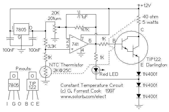
This circuit was built to stabilize a radio frequency VFO (Variable Frequency Oscillator) for ham radio applications. The circuit has also been used to lower the drift of a Ramsey FM10a micropower FM transmitter. More: The 7805 voltage regulator...
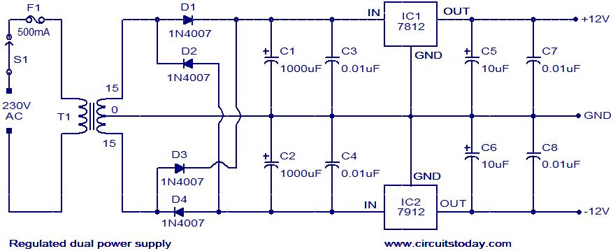
The circuit described is a regulated dual power supply that provides +12V and -12V from the AC mains. Such a power supply is an essential tool for electronic hobbyists. The transformer T1 reduces the AC mains voltage, while diodes...
The welder no-load power saver circuit consists of a current detection control circuit and a power saving control circuit, as illustrated in the accompanying chart. The current detection control circuit includes a current transformer (TA), a bridge rectifier (UR),...
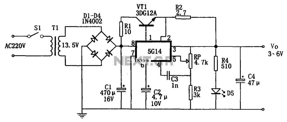
As shown in the figures, this is a practical adjustable power supply. It utilizes an integrated voltage regulator (5G14) in conjunction with a 3DG12A transistor for current spreading, providing an output voltage range of 3 to 6V. The rated...
This project page has evolved into a design discussion. Constructive suggestions and collaboration are still welcome. Please refer to the comments section. The project focuses on the development of an electronic circuit design, which has transitioned from a simple project...
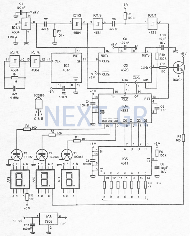
This compact device, designed primarily for modelers, provides instantaneous readings of pulse duration in milliseconds (ms). It can measure servomotor positions, typically ranging from 1 ms to 2 ms, and can also perform repetitive or non-pulsed measurements, such as...