
High Precision Digital Pulse Meter Circuit

Features include:
- Measurement range from 0.01 ms to 9.99 ms with a resolution of 10 µs.
- Visual self-testing indicators during activation.
- Scale underestimation for values exceeding 9.99 ms.
- Memory function for instantaneous pulses.
- Powered by a 9V battery.
- Power consumption approximately 110 mA to 130 mA.
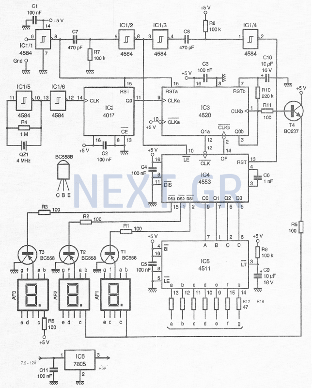
The circuit operates using a conventional 4 MHz crystal, which corresponds to a 0.25 ms period, necessitating a multiplication by 40. The integrated IC2 functions as a decimal counter, multiplying by 10, while half of IC3 (a binary counter) multiplies by 4. The output results in a measurement of 40 x 2.5 µs = 10 µs. This measurement is processed by circuit IC4 (4553) at terminal 12 (CLK input). Given the 10 µs resolution, for instance, if the input signal comprises 160 bits of 10 µs, the total duration would be 160 x 10 µs, equating to 1.6 ms.
The input signal is generated via the R7/C7 network and IC1/2, producing a LE signal of approximately 30 µs. This signal triggers the 4553, which subsequently blocks the enumeration results on the indicators, effectively storing the measurement. The termination of the LE pulse generates a RESET pulse at terminal 13 of IC4 after passing through IC1/3, R8/C8, and IC1/4, preparing the system for the next measurement. The RESET pulse resets the counter to zero while updating the display. As long as LE remains at +5V, the data remains accessible at the output, which is multiplied at a defined rate by capacitor C6 and decoded by IC5 (7-segment decoder, 4511).
The R9/C9 circuit at terminal 3 (LT) enables a low-power mode during the initial activation of the meter, allowing for an auto-test of all segments to verify functionality. Transistors T1, T2, and T3 control the cathode of each indicator without overloading IC4 (4553). Resistor R6 delineates the threshold between ms and ms for instantaneous readings. Resistors R12 to R18 limit current to the indicators to prevent degradation.
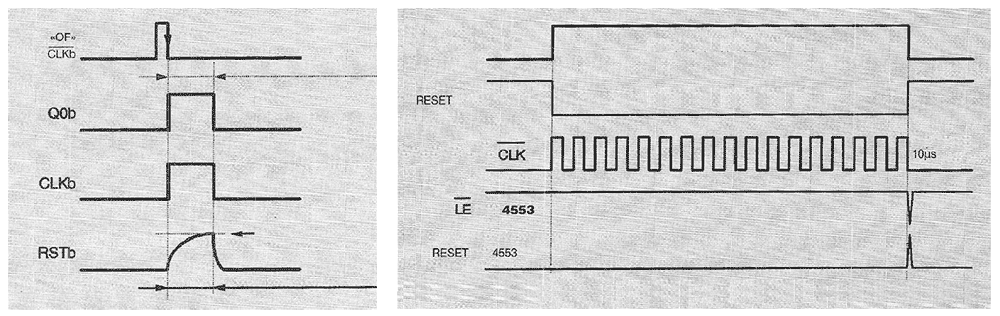
Key features include instantaneous readings in ms, 10 µs resolution, memory function, and self-testing capability. The design also incorporates a mechanism for indicating when the measurement exceeds the available scale, utilizing the second half of the binary counter 4520 (IC3) for this purpose. The OF445 output of IC4 emits a positive "OF" pulse if the measured value exceeds 9.99 ms.
In normal operation, Q0b has a value of "0," resulting in CLKb also being "0." This condition allows the "OF" indicator to activate, increasing the meter's value. Output Q0b transitions to "1," causing CLKb input to become "1," thereby blocking the counter.
Transistor T4 manages the scanning of the two AF1 and AF2 points, recording any instances of exceeding the measurement range. The counter must be disengaged to account for this overrun, which is indicated as a fixed reading. To facilitate this, the R10/C10 loop is included, which slowly transitions Q0b to "1," sending a reset to the RESET input after approximately one second. The two points will extinguish, and Q0b and CLKb will reset to "0," preparing the counter for potential future overruns.
It is important to note that scaling is not retained as it automatically resets. The IC6 circuit stabilizes the power supply at +5V, while capacitors C1 to C5 and C11 filter noise from the power lines.
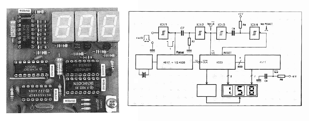
The printed circuit board is single-sided, measuring approximately 63 x 66 mm. Initial assembly involves attaching three bridges: a small one located beneath the AF1 indicator, another beneath IC4, and the third to the left of IC2. Subsequently, the integrated circuits should be secured, preferably using low-profile components for optimal fit. The assembly continues with the placement of resistors, capacitors, the crystal, and the 5V stabilizer (IC6), which should be firmly attached to enhance durability and heat dissipation.
Testing begins by applying power (e.g., via a 9V battery) at the designated "+", and "GND" points adjacent to IC6. Verification of +5V at the terminals of one of the filtering capacitors (C1 to C5 or C11) is essential. After disconnecting the battery, transistors should be soldered in their correct orientations, followed by the careful installation of integrated circuits and indicators. The signal input is connected to the 'INPUT' and 'GND' points adjacent to resistor R4.
For activation, short the "INPUT" and "GND" and power on the circuit; the expected readings should initially display 8.88 (self-test), followed by 0.00 (measured value). In modeling applications, a small 3-pin connector can be constructed to facilitate insertion of the circuit between the receiver and the servo drive.
Expected readings should fall between 1 ms and 2 ms, depending on the position, without interfering with the receiving device. It is normal to observe a deviation in the servo drive when the counter is not powered. This device proves highly beneficial for configuring remote-controlled setups, particularly for adjusting pulse-width modulation encoders.
Components used include:
- Resistors: R1-R3: 100Ω, R5, R6, R11: 100Ω, R4: 1MΩ, R7, R8, R9: 100K, R10: 220KΩ, R12-R18: 47Ω
- Capacitors: C1-C5, C11: 100nF, C6: 1nF, C7, C8: 470pF, C9, C10: 10µF / 16V
- Integrated Circuits: IC1: 4584, 40106; IC2: 4017; IC3: 4520; IC4: 4553; IC5: 4511; IC6: 7805
- Transistors: T1-T3: BC558; T4: BC237
- Indicators: AF1-AF3: Common Cathode 13mm TDSR5160
- Crystal: QZ1: 4MHz HC49 / 4HThis small device, intended primarily for modellers, allows an instant reading of the time I of a pulse in ms. It can, for example, measure the position of the servomotors, about 1 to about 2 ms, or make repetitive or non-pulsed measurements, such as closing or opening times of any instrument, parasitic abnormality.
The diagram just describes the operation of this device. The pulse to be measured is displayed at the input of the inverter IC1 / 1 trigger gate. This gateway allows a slight reset of the signal format and displays an input impedance high enough to not disturb the signal. The output of the IC1 / 1 disables the counters 4017 and 4520 (IC2 and half IC3).
Features
• Measurement range between 0.01ms and 9.99ms with a resolution of 10μs
• Visual self-testing of indicators during activation.
• Underestimation of scale (> 9.99mS)
• Memory function for instantaneous pulses
• 9V battery supply
• Power consumption approx. 110mA to 130mA
The Main Operation of the Circuit
If a conventional 4MHz crystal is selected and corresponds to a 0.25 ms period, we will have to multiply by 40.
The integrated IC2 is a decimal counter that will perform the multiplication by 10 and half IC3 (double binary counter ) Will multiply by 4.
At exit, we will have the presence of 40x 2.5μs = 10μs. They are measured by circuit 4553 (IC4) at terminal 12 (CLK input). Given the 10μs resolution, for example, if there are 160 bits of 10μs, the input signal is 160x10μs, that is, 1600μs, so 1.6ms.
Input of the input signal is generated Thanks to the R7 / C7 and the integrated IC1 / 2, a LE signal with a duration of about 30μs. This, which allows the triggering of 4553, which will send and, most importantly, block the result of enumeration in the indicators (memorization).
The end of the LE pulse will in turn produce a RESET pulse at IC4 terminal 13 after one pass from IC1 / 3, R8 / C8 and IC1 / 4 to prepare it for the next measurement. This RESET pulse will reset the counter to zero but will change the display. As long as LE is always at + 5V, the data remains available at the output. They are multiplied at a determined velocity by capacitor C6 and decoded by IC5 (7-segment decoder, 4511).
Observe the R9 / C9 circuit at terminal 3, LT.
Its components allow each moment the meter starts to apply a low-power mode momentarily to command the activation of all segments (auto-test with activation) and to verify that there is no problem. Transistors T1, T2, T3 control the cathode of each indicator without loading IC4 (4553). Resistor R6 shows the split point between ms and ms to get an instant read. Resistors R12 to R18 limit the current to the indicators to avoid any degradation.
We have the key features in this way.
Instant reading in ms, 10μs resolution, memorization and self-test. We still have to study the depiction of exceeding the available scale. In fact, for reasons of simplicity, we preferred to use the second half of the binary counter 4520 (IC3) and remain free. The OF445 output of IC4 produces a positive "OF" pulse if the scale is exceeded (if the value is greater than 9.99 ms).
In normal mode, Q0b has the value "0", so the same thing happens with CLKb.
It is therefore the frontal cavity of "OF", which will increase the value of the meter. Output Q0b will overcome status "1". Because of this, CLKb input is at "1" and blocks the counter.
Transistor T4 controls and scans the two AF1 and AF2 AF points by recording an excess of the available range. The counter must now be disengaged to overcome this overrun, which remains as a fixed indication. For this reason, the R10 / C10 loop is added slowly (since Q0b passes to "1") and sends a reset to zero at the RESET input after about one second.
The two points are extinguished. The Q0b and CLKb are reset to "0" and the counter is ready for the case of a new overrun of the scale.
Important Note: Scaling is not memorized as it automatically turns off. The IC6 circuit allows the power supply to stabilize at + 5V. Capacitors C1 to C5 and C11 filter the parasites on the feed lines.
The Construction
The printed circuit, which is single-sided, has dimensions of about 63 x 66mm.
Figure 5 shows the mounting of the components on it. Glue first of all three bridges. The first, which is very small, is located just below the AF1 indicator. The second is under IC4 and the third left of IC2. Then paste the terminals of the integrated circuits. It is better to place the markers on bases to lift them as high as possible to fit them into the box. In this case, use a low profile crystal for QZ (about 4mm high) if necessary. Glue the resistors, capacitors and then the QZ crystal. Now stick the 5V stabilizer, the integrated IC6 and screw it onto the circuit for greater robustness and to get the maximum heat.
Tests
Feed the circuit (for example, with a 9V battery) at the "+" and "GND" points on the left of the IC6.
Verify the presence of + 5V at the terminals of one of the filtering capacitors (C1 to C5 or C11). Disconnect the battery. Glue the transistors in the direction of their placement. Place the integrated circuits (caution in their turn) and all three indicators in their place. The signal input is at the 'INPUT' and 'GND' points from the left part of the R4 resistor.
Activation
Short the "INPUT" and "GND" and turn on the circuit, you should read 8.88 (self-test), then 0.00 (measured value). For use in modeling, you can build a small 3-pin fitting connector that allows the circuit to be inserted between the receiver and the servo drive.
You should therefore read values between 1 and 2ms, depending on the position, without harassing the whole of the receiving device.
It is, on the contrary, normal to observe a deviation of the servo drive when the counter is no longer being fed. This device proves extremely useful for setting up remote-controlled sets, in particular for adjusting pulse width modulated encoders.
Components
R1-R3: 100Ω
R5, R6, R11: 100Ω
R4: 1MΩ
R7, R8, R9: 100K
10: 220KΩ
R12-R18: 47Ω
C1-C5, C11: 100nF
C6: 1nF
C7, C8: 470pF
C9, C10: 10μF / 16V
IC1: 4584, 40106
IC2: 4017
IC3: 4520
IC4: 4553
IC5: 4511
IC6: 7805
T1-T3: BC558
T4: BC237
AF1-AF3: Common Cathode 13mm TDSR5160
QZ1: crystal 4MHz HC49 / 4H
Related Circuits
Trimming is straightforward when matched NPN transistors are utilized for Q1 and Q2, along with 1% tolerance resistors for R6 to R11. A dual trace oscilloscope, digital voltmeter (DVM), and sine wave generator are required for this process. Although...
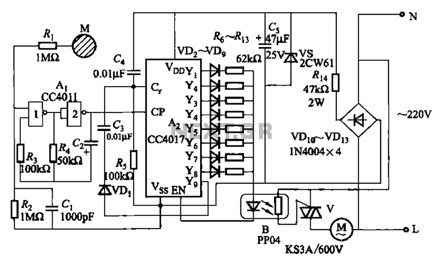
The circuit depicted in Figure 3-7 utilizes a touch sensor chip in conjunction with a conductive sheet. It is designed to achieve eight different speed settings. The CC4011 timing pulse oscillator is comprised of an integrated circuit. The configuration...
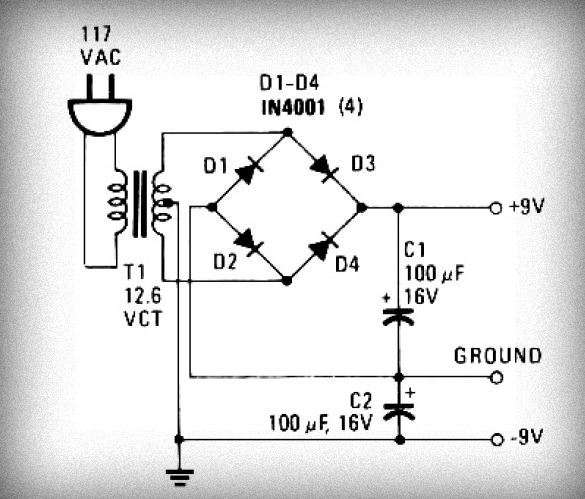
Initially, voltage from AC 220V or 110V enters the transformer, which reduces it to 12V AC. This AC voltage is then rectified using either four diodes or a bridge rectifier to convert it to DC voltage. The resulting DC...
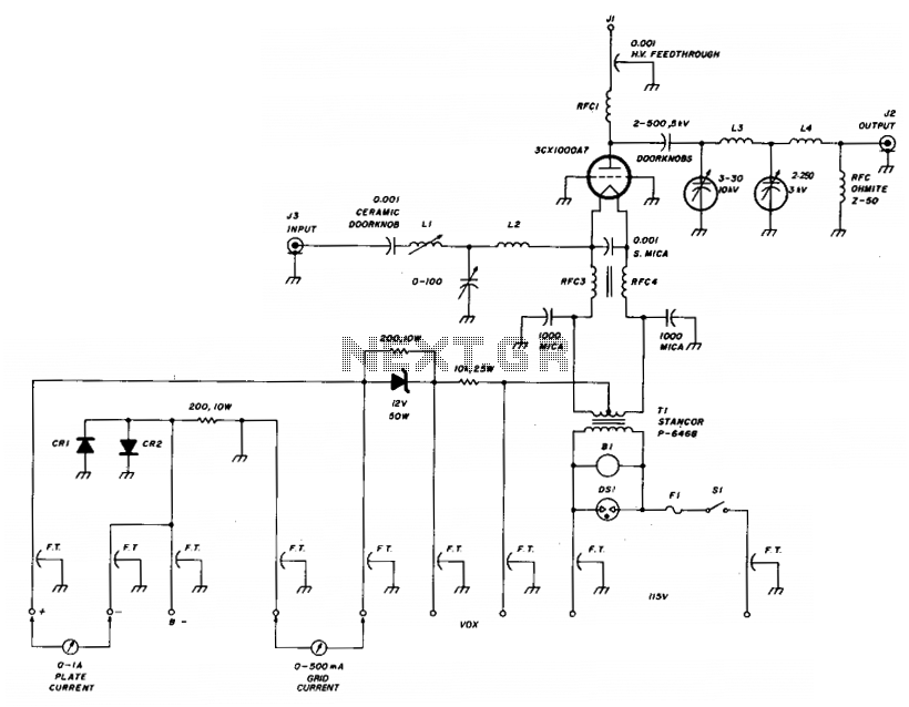
The amplifier utilizes a grounded grid circuit featuring either the Eimac 3CX1000A7 or 8877 ceramic/metal triodes designed for linear operation within the HF and VHF frequency ranges. It delivers a legal power output of 1500 watts PEP and continuous...
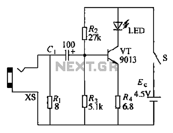
The circuit operates as a light-to-sound conversion system, featuring a light electric sound conversion circuit with two simple fiber optic connectors for experimental purposes. The electrical diagram illustrates the conversion circuit, where audio signals from a radio, music player,...
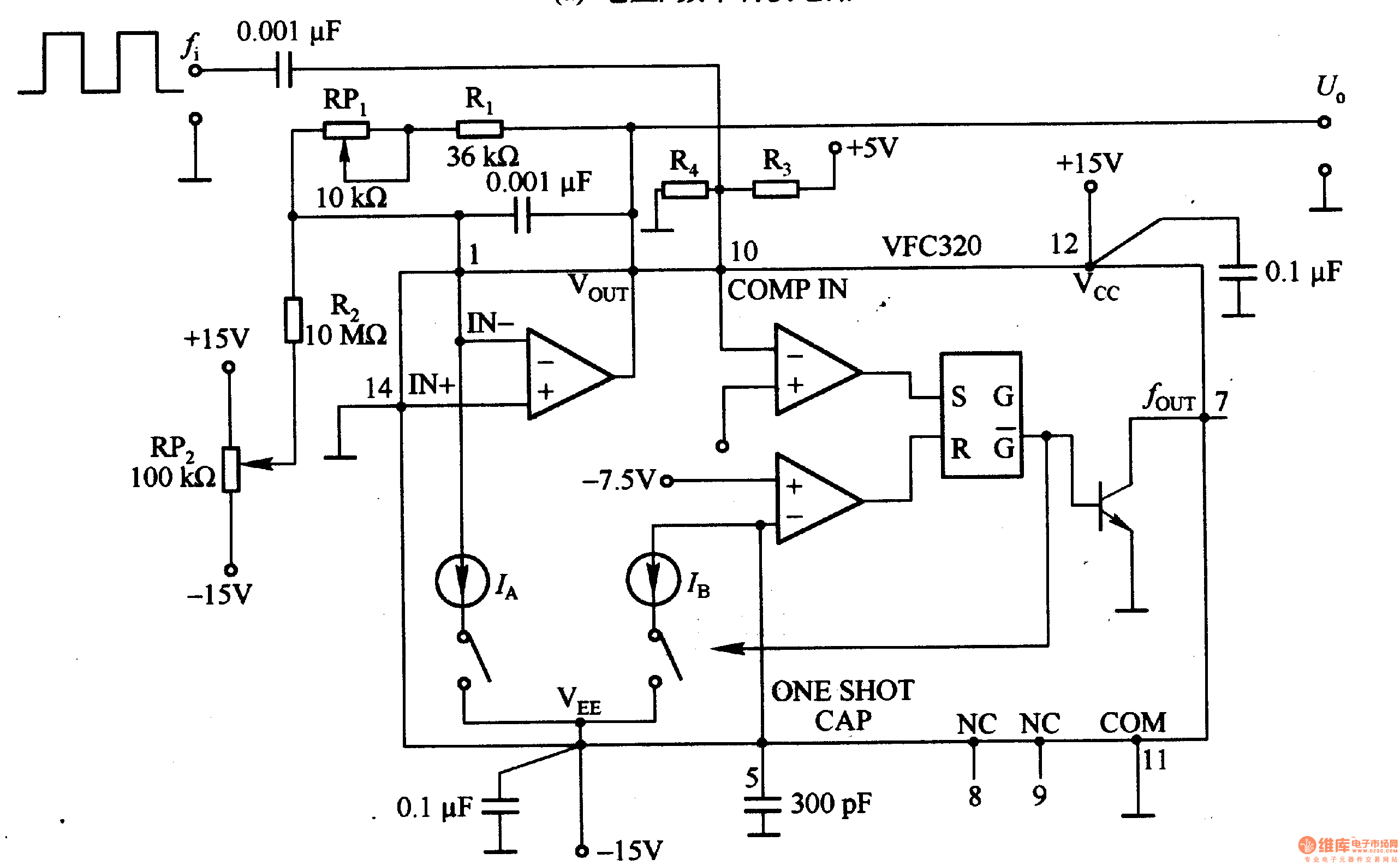
Figure 1-22 (a) illustrates a circuit that converts an input voltage of 0 to +10V (Ui) into a pulse with an output frequency ranging from 0 to 100kHz. In this configuration, pin 7 of the VFC320 is connected to...