
high power regulator
The half-linear design serves as an efficient method for managing thermal dissipation in linear voltage regulators, particularly when the power requirements are modest, such as in the 1-5W range. This contrasts with traditional designs that may need to dissipate significantly more heat, up to 75W per rail. The operational characteristics of MOSFETs are emphasized, particularly their inherent gate capacitance, which can introduce latency in response to rapid load changes. This necessitates a careful selection of drive circuitry to ensure optimal performance in dynamic conditions.
In scenarios where low noise is essential, op-amp regulators can be employed; however, it is critical to note that any regulator with a set pin can be configured to maintain a stable output voltage, even extending down to zero volts with minimal current draw. This flexibility allows for a broad range of applications, from precise low-voltage supplies to more robust power management systems.
The LT3080 is highlighted as a versatile component in high-power applications, capable of driving substantial loads—over 300W—when paired with appropriate current amplifiers and power transistors. The use of Q2 as a current amplifier enhances the thermal performance of the system by distributing heat away from the LT3080, which is kept cool through careful design choices, including the limiting of output current to 40mA.
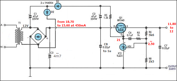
The transformer design is crucial in this schematic, where the winding ratios must be optimized to ensure adequate voltage levels under load. The recommendation for a 13.5:1 primary to secondary ratio is based on the need to deliver 16V at a 5A load, accounting for dropout voltage and wire gauge to minimize resistive losses. The construction of the transformer from E-core pieces salvaged from microwave transformers presents a practical approach to achieving the desired inductance and efficiency.
In summary, this design emphasizes the importance of thermal management, component selection, and transformer design in creating efficient and reliable power supply circuits. The integration of the LT3080 with high-performance transistors and careful attention to winding configurations will yield a robust power stage capable of handling varying load conditions while maintaining stability and efficiency.The half linear design is simply so you can get away with small thermal considerations, if the linear only needs to handle 1-5w in place of the full 75w per rail. as for the MOSFET to regulate with them means operating them in there linear region, just below the rated voltage for rson, however mosfets are not ideal for a supply as they have gate c
apacitance delaying there response to transients unless driven quite hard As for op amp regulators being noisy its is partly correct was just throwing up the option any regulator with a set pin can function adequately pulling it below zero with some pissy little milliamp rated winding is all thats required, and allows an output voltage down to zero, with how much voltage just being the net offset voltage of the regulator and the pass element personally prefer to not have a piece of metal close to or exceeding 100 degrees in my lab, but if you wish to go linear then by all means sounds like you have the pieces to do it. As a secondary throught if you went with full linear how would you isolate you few thousand uF capacitors from boiling eevblogfan, here is a couple of suggestions on how to use the LT3080 to drive a 300+ W power stage.
Q2 is a (low saturation voltage) current amplifier that drives two (or more) forced air cooled 150W (or more) power transistors. Of course, to fully utilise the LT3080 capabilities you might need faster power transistors than the 2N3772/2N3055 shown at the drafts.
Additionally, if your LT3080 drives a power stage instead of the load directly, R8 shuts the power stage off, providing the first milliamperes to the load by the LT3080 itself and after that the power stage takes over; R9 ensures that the LT3080 will never provide more than 40mA, keeping it always cool on the PCB -no need to mount it in the hot heat-sink and have its characteristics drift off. sorry about that, combination of overlooking the junction and iphone "auto-correct" still as for a mosfet, i am really struggling to find a design that responds to wide variations in loads, if uses a voltage doubler arrangement to get enough voltage to properly drive the mosfet, though you could well just use another puny winding to get a higher one, as for the actual transformer, i assume you know the number of windings in the primary and how to calculate how many you will need on the secondary, if not just post the number on the primary, and the gauge of wire your using, (will be a voltage drop in the windings that needs to be compensated) to go furthur into that circuit, it would seem that the higher voltage is being fed in and being pulled down for control.
with some feedback off the output, then fed into an adjustable voltage reference to keep it accurate and stable, now just at a guess, i am going to guess your going to remove that and wind on your own with thinner gauge wire, if so, count the number of turns, at the moment the ratio is somewhat close to 52:1 primary to secondary, however you will need to bring that close to 13. 5:1 to get it able to handle 16V under a 5A load, 16V as you will have some drop out voltage, as for the guage of wire, i would say something close to 2.
5mm CSA, or AWG10, you can get away with less, this is just trying to keep the temperature increase in the windings down, any neagtive or positive biasing windings can be as low as AWG30 as its milliamps, the "big transformer" is 2 "E" core out of 2 microwave transformers, and they re held together with a"hand held vise ", so in order to "rewind" I just have to release the vise and then pole the windings out of it BTW, I don`t have 10AWG winding wire, and I remember someone has told me that as the thickness of the winding wire goes low, so as the loss of the copper goes low, is that true if so, I think I have like 150 meter`s long 18AWG or so, is that better one I mean, 18AWG can pass about 8A no problem ( ) almost any diode will die with that sort of current, h 🔗 External reference
Related Circuits
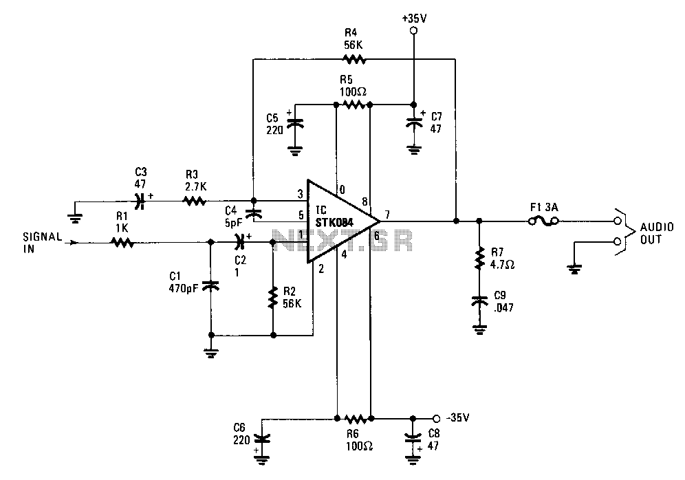
The input is AC coupled to the amplifier through capacitor C2, which blocks any DC signals that may also be present at the input. The combination of resistor Rl and capacitor Cl forms a low-pass filter, effectively eliminating unwanted...
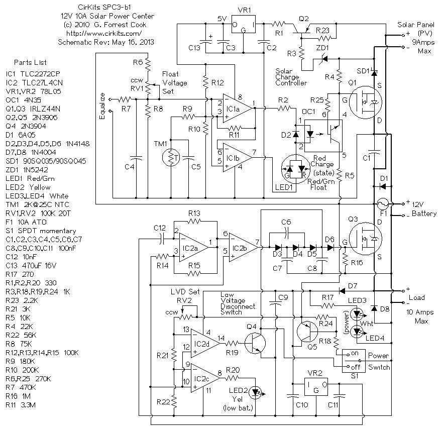
The SPC2 is a solar power center, it can be used to handle all of the power functions for small 12 Volt solar powered devices. It contains a photovoltaic charge controller and a low voltage load disconnect circuit. The...
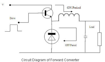
Switched Mode Power Supplies (SMPS) are categorized as DC to DC converters and DC to AC converters. Switched Mode Power Supplies (SMPS) are essential components in modern electronic devices, providing efficient power conversion from one form to another. The primary...
Envision a master controller device that manages other devices within a household without the need for additional wiring to facilitate data transmission. The concept of a master controller device serves as a central hub in a smart home ecosystem, enabling...
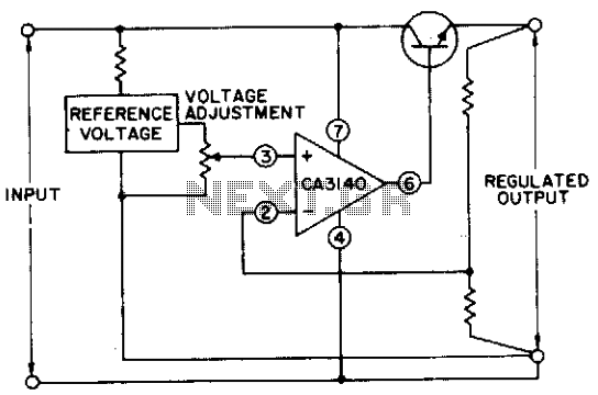
The circuit utilizes a CA3140 BiMOS operational amplifier that is capable of providing a regulated output adjustable from approximately 0 to 24 volts. The circuit is fully regulated. The CA3140 BiMOS operational amplifier is a versatile component that combines the...
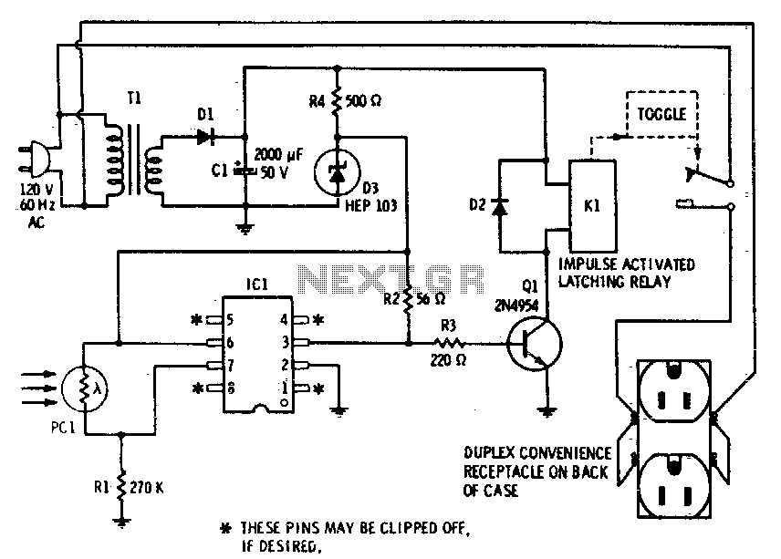
This device enables remote control of AC-powered appliances by utilizing the beam of a flashlight as a triggering mechanism. A key feature of this gadget is its memory function; activating it once supplies power to the device, and it...
Warning: include(partials/cookie-banner.php): Failed to open stream: Permission denied in /var/www/html/nextgr/view-circuit.php on line 713
Warning: include(): Failed opening 'partials/cookie-banner.php' for inclusion (include_path='.:/usr/share/php') in /var/www/html/nextgr/view-circuit.php on line 713