
Sine to rectangular wave conversion circuit
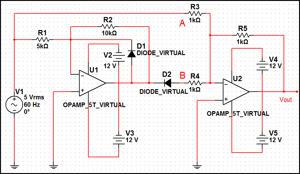
The Schmitt trigger circuit is a vital component in signal processing, particularly for converting analog signals into digital signals. It utilizes positive feedback to create hysteresis, which enables it to provide a clean transition between high and low states. This characteristic is particularly useful when dealing with noisy input signals, such as sine waves, which can fluctuate around the threshold levels.
In a typical Schmitt trigger configuration using an operational amplifier (op-amp), the circuit includes two resistors that set the upper and lower threshold voltages. The op-amp is connected in a non-inverting configuration, where the input sine wave is fed into the non-inverting terminal. The output of the op-amp switches states based on the input voltage crossing the predefined thresholds.
The key parameters of the Schmitt trigger circuit include the reference voltages, which can be adjusted by varying the resistor values. This allows for customization of the threshold levels according to the specific requirements of the application. The output of the circuit is a square wave that corresponds to the input sine wave, effectively eliminating any noise and providing a sharp transition between high and low states.
In summary, the Schmitt trigger circuit is an effective solution for converting sine waveforms into rectangular waveforms, ensuring reliable performance in digital signal processing applications.The best Op-Amp circuit which is used to convert sine waveform into rectangular waveform is the schmitt trigger circuit 🔗 External reference
Related Circuits
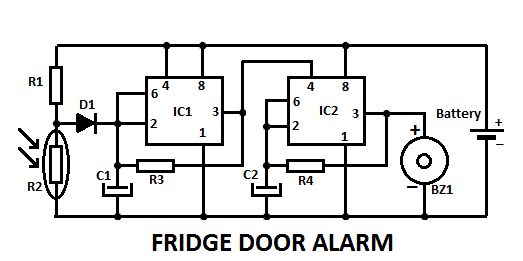
This fridge door alarm operates using a 3V battery supply and should be placed in a small box inside the fridge, near the lamp or close to the opening. The fridge door alarm circuit is designed to alert users...
The metal detector circuit comprises an oscillator and a sound-light alarm circuit. The oscillator circuit includes an inductor (L), a capacitor (C1), a sensor switch integrated circuit (IC1) that integrates the oscillator, detector, comparator circuit, and peripheral components. The...
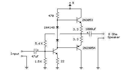
This weblog focuses on electronic circuit schematics, PCB design, DIY kits, and electronic project diagrams. The following describes a small audio amplifier, similar to those found in medium-sized transistor radios. The input stage is biased to ensure equal power...
When the water level is below the steel rods, there is no contact between the metal can and the rods, which are supported by a small insulated wooden board. The small circuit built around IC1 does not draw any...
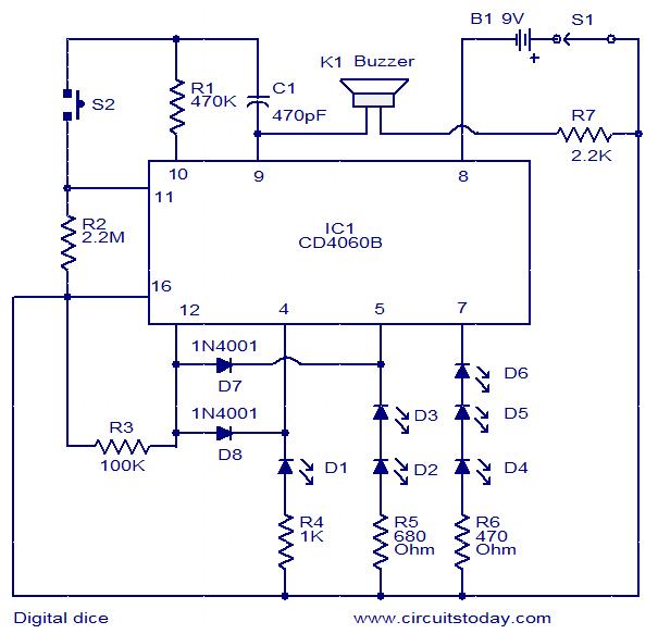
This is a simple and easy-to-construct digital dice circuit. The circuit is based on a single IC, CD4060B. The dice consists of six LEDs marked D1 to D6. The number of LEDs glowing indicates the numeral. The heart of...
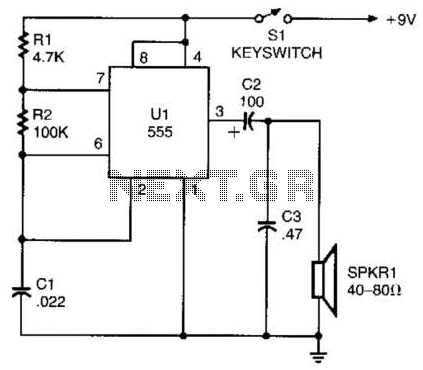
A 555 timer configured as an astable multivibrator is used in this circuit to generate an audio note. The capacitance value can be changed to vary the audio note as desired. The circuit utilizes a 555 timer IC, which...
Warning: include(partials/cookie-banner.php): Failed to open stream: Permission denied in /var/www/html/nextgr/view-circuit.php on line 713
Warning: include(): Failed opening 'partials/cookie-banner.php' for inclusion (include_path='.:/usr/share/php') in /var/www/html/nextgr/view-circuit.php on line 713