
High Quality Valve Amplifier

A notable characteristic of tubes is that their performance can change with operating time. It is advisable for users to monitor the operating time of the tubes and replace them before they fail completely. The construction of tube amplifiers is typically robust, making them challenging to integrate into standard chassis designs.
The construction, wiring, and assembly are based on traditional methods, although a printed circuit board (PCB) is preferred for convenience, particularly for manufacturers. This design takes into account the high operating voltages of the tubes while ensuring sufficient spacing for effective heat dissipation.
The amplifier design features a large printed circuit board with two channels, along with the necessary power supplies. The output transformers and power transformer are separate from the main board.
The theoretical circuit includes an integrated voltage regulator using TL783 and 7812 for the low-voltage sections. The high-voltage feed design follows similar principles.
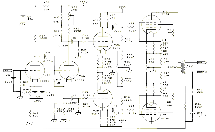
Each channel input is equipped with two levels controlled by three-way switches. As illustrated in the accompanying figure, the signal enters the grid of a dipole triode tube, specifically an ECC81, which functions as a phase splitter and feeds back to the cathode from the AC outlet.
The signal then progresses to the grid of the second triode, exiting through the anode and cathode. The signals from the anodes of the driver tube are sent to the final amplification stage, which consists of two EI34 tubes configured in a push-pull arrangement. Intermediate passive components are employed to regulate non-operational characteristics that could affect the performance of the tubes.
Key considerations include ensuring that the waveforms at the outputs of the phase splitter and the driver tube are equal and opposite immediately after the coupling capacitors. This balance is achieved using trimmers that allow for precise adjustments. Additionally, the bias current of the two final tubes must be balanced, which is accomplished with another trimmer. The voltage between the cathode and ground should yield consistent readings.
Capacitors used in the design must be of high quality to withstand the operating voltages. Initially, potentiometers may be used for adjustments but should be replaced with resistors of equal value after tuning is complete.
Setting up the amplifier requires the use of an oscilloscope, a signal generator, and a multimeter. The signal generator is used to measure the output signals from the first dipole triode after the coupling capacitors, and the first trimmer is adjusted to achieve balance. The same procedure is followed for the second stage output of the second dipole triode. To adjust the bias current of the final tubes, the voltage between the cathode and ground is monitored, and the third potentiometer is adjusted to ensure equality.In recent years more and more, have a tendency ket demanded higher reimbursement structures with lights and music lovers in general and manufacturers of tube amplifiers. The reason, in their view is that the sound of tubes is more sweet, how rich and incomparably cleaner, On the other hand, however, the entire structure is much more massive than transistor amplifiers, considerably more expensive, while the operation voltages are very high that require special protection measures to prevent identity risk of electric shock.
The tube structures as key components require fine-tuning, otherwise liable to break. The lights generally resistant but excellent work at very high temperatures without having the need for heatsinks. They just need ventilation. The lifetime of the bulbs is probably less than that of a transistor but it does warn the iote be burned as opposed to transistor destruction is sudden.
A feature of the tales is that their features altered by the operation time. Too friends count the running time of lights and change before ruin completely. A building with lights and was always a heavy construction difficult is it going even in the chassis in the classical sense. The construction, wiring and equipment were on the bases and koses. In our own but we preferred a printed kyklora, for convenience, mainly apeiroys manufacturers, of course, taking due account of the high voltage which lights are working, but the distance from examtimaton itlaketa for better elimination heat.
The amplifier will introduce you to include a large printed two channels proeniochyii the necessary aid and power supplies. Unless the board is of course the output transformers and power transformer. The theoretical circuit fed munity siatheroiioiii includes an integrated voltage with a TL783 and 7812 for the threads of iroenischyti.
The plan is the same as the fed ment of high voltage is the same issue. At the entrance of each channel eniochytikes two levels with two three-way. As in Figure 1 appears below the signal enters the grid diplotriodou a tube in our case is an ECC81 which plays the role of Phase splitter and enters the cathode sira feedback from the AC outlet. Then oima the rise heading in the grid of the second triacs and leaving the anode and cathode. Then the signals from the anodes of the guide tube run in the final stage payment consists of two EI34, connected to a push ryll.
Intermediate materials are passive and are used to regulate non-operating trends affecting the other characteristics of the bulbs. Some points that will in thoume are: As we waveforms at the outputs of Phase splitter and the driver tube, immediately after the coupling capacitors must be equal and opposite.
This is achieved using trimmers which when rotated allowing the perfect balance of waveforms. Another point is to balance the bias current of the two final tales. This is accomplished with another trimmer. By measuring the voltage between the cathode and earth should have the same indication. The number of capacitors must be of good quality to withstand voltage. The potentiometer stuck temporarily replaced by resistors equal value after adjustment. The setting of the amplifier is made using an oscilloscope, a sound generator and a multimeter. Giving a signal generator are measured by an oscilloscope signals at the output of the first diplotriodou after the coupling capacitors and rotating the first trilateral balance just two marks. The same with the second stage outlet diplotriodou second. To adjust the bias current of the two end lights, count the voltages between cathode and earth, and after turning the third potentiometer (wire) to equate.
🔗 External reference
Related Circuits
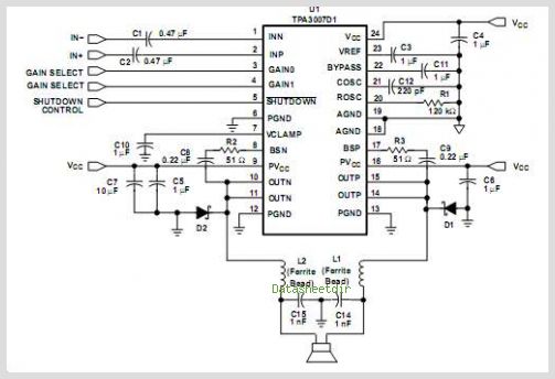
The TPA3112D1 is a 25-W efficient Class-D audio power amplifier designed for driving a bridge-tied speaker. It incorporates advanced EMI suppression technology, allowing the use of cost-effective ferrite bead filters at the outputs while complying with EMC requirements. The...
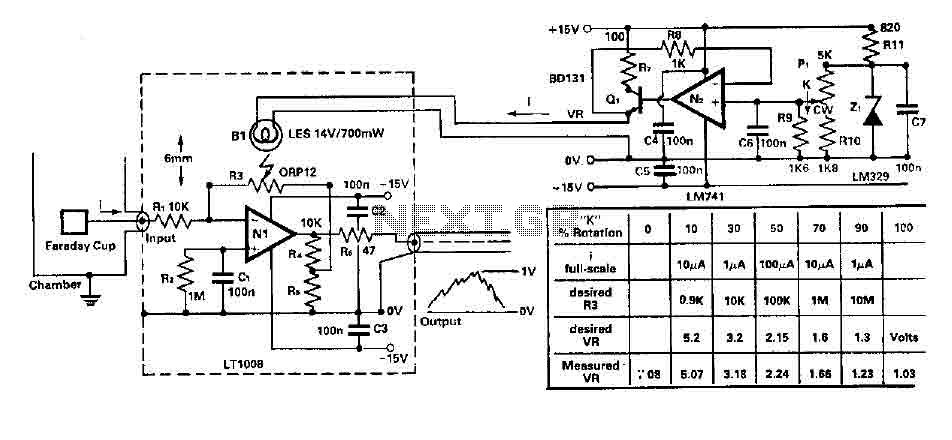
To amplify small current signals as an electron collector inside a vacuum chamber, it is advantageous for reasons related to noise and bandwidth to have a "head-amplifier" connected to the chamber. Operational amplifier 1 is a precision device featuring...
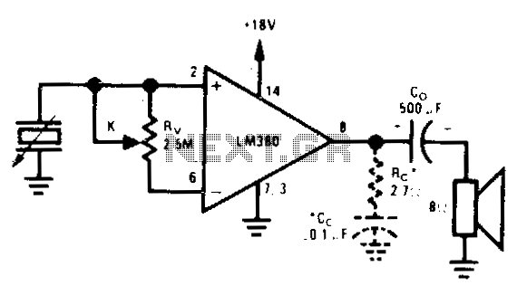
Used when maximum input impedance is required or when the signal attenuation of the voltage divider volume control is undesirable. In electronic circuit design, achieving maximum input impedance is often critical, particularly in applications involving sensitive signal processing. The use...
A small headphone amplifier is a valuable device capable of driving multiple pairs of headphones. The headphone amplifier's task is simplified due to the relatively low output power requirements and the manageable load characteristics. Headphones generally have an impedance...
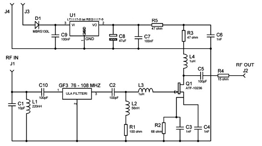
A Selective Amplifier 10dB for FM/VHF region. Note that some devices to be used SMD components and may have a minimum sales volume. Device works very well as an FM external amplifier "when used for example in car /...
This simple circuit is designed to provide an output power of approximately 1 watt when connected to a 9-volt power supply. The key advantage of this circuit is its use of a dual Darlington configuration, which increases the input...