
Power Amplifier 6
The increasing popularity of MP3 players, particularly those in a memory-stick format, highlights the need for portable sound systems. However, these devices often lack sufficient power for shared listening experiences. This circuit addresses that limitation, offering a solution for enhancing audio output.This simple circuit was a presented, it can give power output about 1 watt, when connected to a power supply 9 volt. The advantage of this circuit is that it uses a dual darling ton to increase the size as much as of input impedance about 20 Meg ohm.
This circuit unlike other circuits, the input impedance is a constant about 20 Meg ohm always, wheth er to adjust the volume control on any level. The components in the circuit, it is cheap, especially the BC549 transistor output number when the increase will be very distorted, it must reduce the current level to a safe By reducing the volume down. The sector output for the R1 and C1 in order to reduce the oscillator gain is, the fact that the output sector, including an op-amp acts drive dual complementary.
The electrical signals from transducer, Sometimes, it is value less too, For input to the circuit to convert signals from analog to digital. To achieve a satisfactory, We need a power amplifier, who can tell strength of the input signal is simple.
This can extend the input signal from the transducer is 10 times and 100 times. Circuit consists of op-amp IC1 No. 741, To give the appearance of non inverting circuit, R1 is configured input impedance switches. In this the 75 kilo ohms, negative feedback circuit consists of R3 or R4 together with R2, which defines the gain of the circuit. Power supply for this circuit requires two sets of power supply positive and negative, which was in the range of positive, negative 6 volts to the positive, negative 15 volts, in this value add, subtract 9, because available with 9-volt battery immediately.
This circuit is able to identify PAL and NTSC video signals. Its output is high for an NTSC signal and low if the signal is PAL. This output signal can be used, for example, to automatically switch in a colour subcarrier converter or some other device while an NTSC signal is being received. One application is for the reception from satellites of free-to-air` TV signals, which in Australia generally contain a mixture of 625-line PAL and 525-line NTSC programs.
Operation of the circuit is as follows. IC1 is an LM1881 video sync separator which takes the video input signal and generates vertical synchronisation pulses. For an NTSC signal, these pulses are 16. 66ms apart, corresponding to the 60Hz field rate, while for a PAL signal they are 20ms apart, corresponding to the 50Hz field rate.
The vertical sync pulses are fed into IC2a, the first of two dual retriggerable monostable multivibrators in the 74HC123A. IC2a has a period of very close to 17. 9ms, set by the 200kO resistor and 0. 22 µF capacitor at pins 14 & 15. Because the monostable is retriggerable, NTSC sync pulses arriving every 16. 66ms will keep its Q output, at pin 13, high. [. ] The video amplifier in the diagram is a well-known design. Simple, yet very useful, were it not for the ease with which the transistors can be damaged if the potentiometers (black level and signal amplitude) are in their extreme position.
Fortunately, this can be obviated by the addition of two resistors. If in the diagram R3 and R4 were direct connections, as in the original design, and P1 were fully clockwise and P2 fully anticlockwise, such a large base current would flow through T1 that this transistor would give up the ghost. Moreover, with the wiper of P2 at earth level, the base current of T2 would be dangerously high. Resistors R3 and R4 are sufficient protection against such mishaps, since they limit the base currents to a level of not more than 5 mA.
Shunt capacitor C4 prevents R4 having an adverse effect on the amplification. MP3 players are all the rage these days. The smaller ones in memory-stick format are particularly easy to take with you; your very own personal sound system` on the move! It`s when you want others to share your taste in music that you nd these players to have a lack of power.
You can get round this problem with the 🔗 External reference
Related Circuits
Most individuals take the mains AC supply for granted and use it casually without considering its inherent shortcomings and the potential dangers it poses to sophisticated and sensitive electronic instruments and equipment. For ordinary household appliances such as incandescent...
The Hewlett-Packard HSCH-3486 zero-bias Schottky diode is utilized as the detector. To avoid employing a modulation detection method, a chopper-stabilized operational amplifier is implemented. The chopper operational amplifier effectively converts the input DC voltage to AC, amplifies it, and...
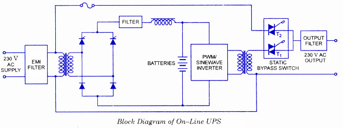
This circuit allows appliances to remain connected to an inverter. While it does not influence weather conditions, it ensures that batteries are safely charged even during periods of generation shortfall. This device is referred to as the Grid Charger...
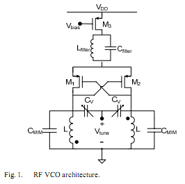
The oscillator is designed to tune from 1.8 GHz to 2 GHz for typical cellular telephony applications. An extended tuning range can be obtained by adjusting the ratio between the varactor capacitance and fixed capacitance in the tank. PMOSFETs...
Powering up twin digital Sony DSC-V1 cameras simultaneously can achieve remarkable synchronization within milliseconds. This is accomplished through the use of dual Sony wired remotes that short the ACC port LANC signal conductor to the ACC port ground. Further...
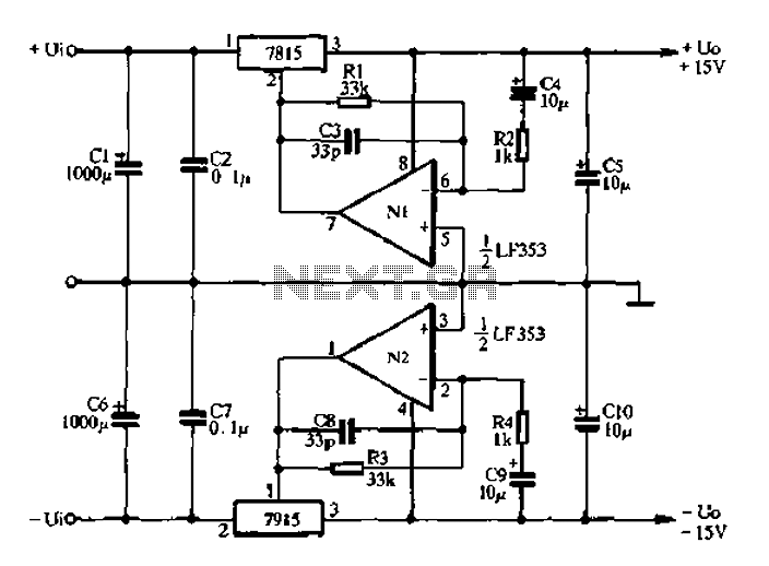
15V active servo power supply circuit The 15V active servo power supply circuit is designed to provide a stable and regulated output voltage of 15 volts, suitable for powering servo motors and other related devices. This circuit typically employs a...
Warning: include(partials/cookie-banner.php): Failed to open stream: Permission denied in /var/www/html/nextgr/view-circuit.php on line 713
Warning: include(): Failed opening 'partials/cookie-banner.php' for inclusion (include_path='.:/usr/share/php') in /var/www/html/nextgr/view-circuit.php on line 713