
High resistance distribution circuit

The high-impedance distribution circuit is designed to maintain stable voltage levels across various loads while minimizing the impact of short circuit conditions. The resistor R1 serves as a critical component in this configuration, providing current limiting functionality that protects both the power supply and connected loads from excessive current during fault conditions. The selection of R1 at a value significantly higher than the battery's internal resistance ensures that, during a fault, the circuit can effectively control the flow of current, thereby reducing the risk of damage to sensitive components.
The interaction between R1 and the shunt resistor Rr plays a vital role in voltage regulation. By carefully selecting these resistances, the voltage stability across the system can be achieved, allowing for consistent performance across all loads. The schematic representation of voltage variation across N and R illustrates how these resistors work in tandem to manage voltage drops and ensure that the system operates within safe limits.
Furthermore, the implementation of a multi-stage high-impedance power distribution system allows for scalability and versatility in various applications. This design can be particularly beneficial in communication systems, where reliability and consistent performance are paramount. The ability to adapt the circuit for different load requirements while maintaining high impedance ensures that the system can handle varying power demands without compromising performance. Overall, this high-impedance distribution circuit is an effective solution for enhancing the reliability and efficiency of modern electronic systems.As shown in the circuit diagram of a high-impedance distribution. It is with low resistivity distribution of certain significant difference is the series resistance in the shunt load current limiting resistor R1, the general value of five times the battery internal resistance ~ l0 times. At this time, if a short circuit shunt occurs, and the system voltage drops are small recoil spike voltage, because R1 limits the short circuit current, and L di / dt is also small sake.
As shown in Figure is N, R schematic voltage variation. Matching the appropriate R1 and Rr, can make N, the voltage change between R within the permissible error range power supply system so that the system load between each independently of each other. Multi-purpose play a shunt to improve the reliability of the communication system. In practical applications, it can evolve out of a multi-stage high-impedance power distribution applications.
Related Circuits
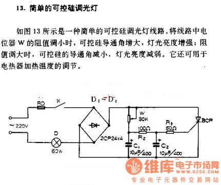
A simple silicon-controlled rectifier (SCR) dimmer circuit is depicted in Figure 13. This circuit is designed to control the brightness of lights. As the resistance in the potentiometer decreases, the conduction angle of the SCR increases, resulting in an...
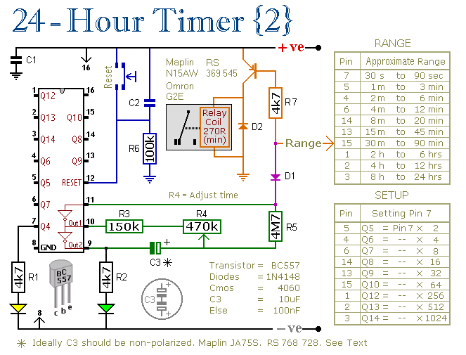
These two circuits are multi-range timers that offer periods of up to 24 hours and beyond. They can function as repeating timers or single-shot timers. Both circuits are fundamentally the same, with the primary distinction being their behavior in...
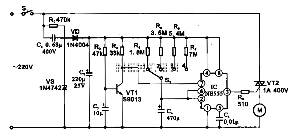
The fan motor driving circuit is depicted as a basic configuration comprising a power circuit and a motor drive circuit. The power supply circuit primarily consists of a power switch (SI), a capacitor (C1), resistors (R1), a Zener diode...
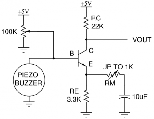
Piezo buzzers are widely used components. When disposing of an old smoke detector, it is advisable to extract the piezoelectric element for future use. Monitoring sound with a piezoelectric element can be challenging due to the low voltage it...
Narrow Band Frequency Modulation (NBFM) is utilized in this 27 MHz transmitter circuit schematic. This circuit is based on the Motorola MC2833 VHF transmitter, which integrates FM modulation and narrow band capabilities into a single chip. P1 is designated...
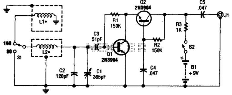
This antenna may assist in minimizing power-line noise. It consists of a plastic hula hoop or conduit with a diameter of 3 feet, which is covered with aluminum foil to serve as a shield for LI and L2. LI...