
Piezoelectric Amplifier Circuit

The piezoelectric element operates on the principle of generating an electrical charge in response to mechanical stress, making it suitable for sound detection applications. The circuit designed by Nerd Kits typically includes an operational amplifier (op-amp) to amplify the small voltage signal produced by the piezo element.
The circuit may consist of the following components: a piezoelectric sensor, an op-amp configured in a non-inverting amplifier configuration, resistors for setting gain and biasing, and additional filtering capacitors to smooth the output signal. The op-amp increases the voltage level, enabling easier processing by microcontrollers or other electronic systems.
To implement this circuit, the piezoelectric element is connected to the input of the op-amp. The gain can be adjusted by selecting appropriate resistor values in the feedback loop. A power supply is required to power the op-amp, which can typically range from a single supply voltage of 5V to 15V, depending on the op-amp specifications.
The output from the op-amp can be connected to an analog-to-digital converter (ADC) for further digital processing or directly to a microcontroller for sound monitoring applications. The circuit can be enhanced with additional features such as LED indicators to provide visual feedback when sound is detected or integrated with a wireless module for remote monitoring.
Overall, this simple yet effective circuit enables the use of piezoelectric elements in sound monitoring applications, demonstrating their versatility and utility in various electronic projects.Piezo buzzers can be found everywhere, next time you throw out an old smoke detector be sure to remove the piezoelectric element from it and stash it in your parts bin. If you want to monitor sound with a piezoelectric element it`s not that easy since the voltage produced by the device is so small.
Nerd Kits has not only provided a circuit to help out they also walk through the circuit and explain it step by step. 🔗 External reference
Related Circuits

The circuit shown will switch on and off a resistive or inductive load up to 800VA with the possibility to adjust both the on and off period. Switching takes place during the zero crossing of the sine wave. The...
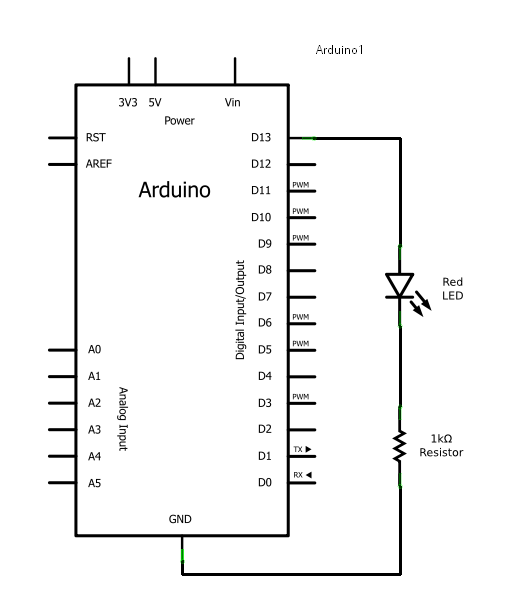
Arduino consists of two main components: the hardware (the Arduino board) and the software (the IDE). The advantage of using Arduino is that circuits can be built and their behavior modified by altering the code instead of changing the...
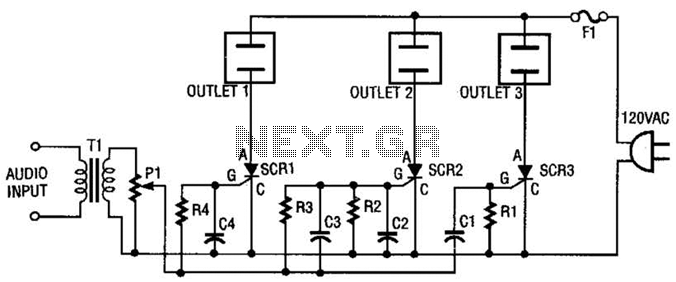
The AC line power is introduced into the circuit through F1, a protective 5-A fuse. One side of the AC line is connected to one side of each AC outlet, while the other side is connected to each silicon-controlled...
A small circuit that can find a lot of applications for measuring time. It has the capability to inform with a sound signal from the BZ1. At the same time, there exists the possibility to drive an external circuit...
Can be directly connected to CD players, tuners and tape recorders. Tested with several headphone models of different impedance: 32, 100, 245, 300, 600 & 2000 Ohms. Schematic shows left channel only. B1, SW1, J1 & C3 are common...

The circuit utilizes a 555 timer integrated circuit (IC) to drive an ultrabright LED. The output generated is a pulsing red light that can be focused using lenses. An ultrabright Stanley LED, which produces an output of 300 millicandela,...