
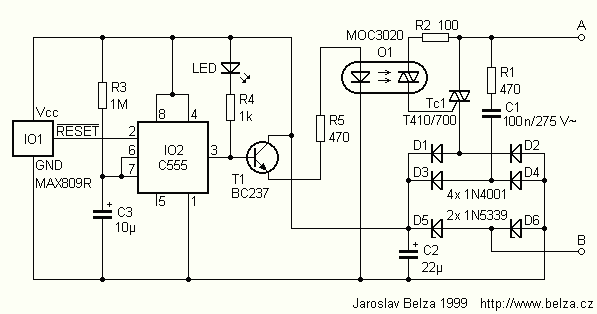
Fan motor driving circuit

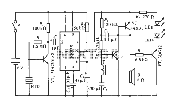
The fan motor driving circuit serves as an efficient mechanism for controlling a fan motor's operation. The power supply circuit is crucial for converting the incoming AC voltage into a usable DC voltage for the motor. The components involved in this conversion process include the power switch (SI), which allows for the control of power flow, and the capacitor (C1), which helps in smoothing out the voltage fluctuations. The Zener diode (VZ) plays a vital role in voltage regulation, ensuring that the output voltage remains stable at around 12V, which is essential for the reliable operation of the motor.
The rectifier diode (VD) is responsible for converting the AC voltage into DC, while the filter capacitor (C2) further smooths the output to eliminate any ripple. The control circuit, centered around the NE555 integrated circuit, is designed to manage the timing and operation of the fan motor. The timing selector switch (S2) allows for adjustments in the operation duration or speed of the fan, providing flexibility based on user requirements.
The charging behavior of capacitor C3 is critical in determining when the motor will start. As the circuit is powered, C3 charges until it reaches a specified voltage. At this point, the transistor (VT1) becomes conductive, which triggers the NE555 IC to change its output state. This change sends a signal to turn on resistor R2, thereby energizing the motor (M) and facilitating its rotation. The entire design emphasizes a balance between simplicity and functionality, making it suitable for various fan applications.Fan motor driving circuit Shown as a simple fan motor driving circuit, which is mainly from the power circuit, the motor drive circuit portion constituted. The power supply cir cuit mainly by the power switch SI, capacitor cJ, resistors Rl, Zener diode vs, rectifier diode VD and filter element capacitor C2 and the like; and a control circuit mainly by the transistor VTI, timing selector switch S2 test machine integration. circuit lC (NE555) and related peripheral element composition. AC 22V voltage through C1 buck, VD rectifier, q filter, vS regulated output DC voltage of about 12 V.
When the power is turned on, 1V to charge the capacitor C3, c3 ends when the voltage rises to the set value, VT1 conduction, the integrated circuit IC pin goes low, the pin output high, so rr2 turned on, the motor M is energized to rotate.
Related Circuits
Described timer to participate in the current circuit switch - bulb without any modification of existing pipelines. Connect the timer is in Figure 1 The time switch has only two outlets, which is connected in parallel to the button...
The primary winding of the first IF transformer lacks a capacitor, indicating that it functions as a single tuned circuit with the primary coil serving solely as an inductive coupling. The routing of the twisted pair cannot be replicated...
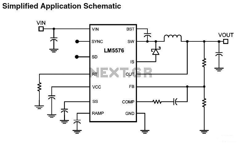
LM5576MHX absolute maximum ratings: (1) VIN to GND: 76V; (2) BST to GND: 90V; (3) PRE to GND: 76V; (4) SW to GND (Steady State): -1.5V; (5) BST to VCC: 76V; (6) SD, VCC to GND: 14V; (7) BST...
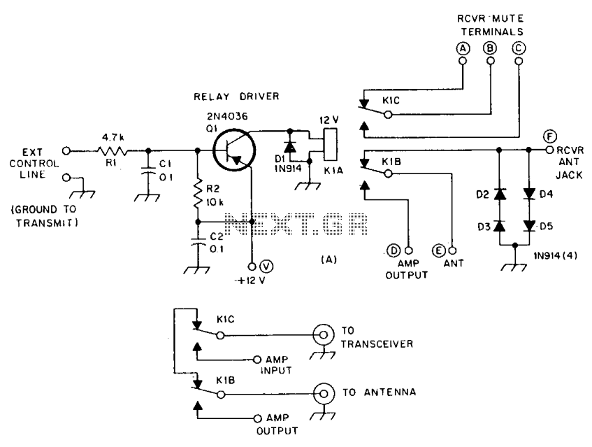
R1 and R2 are carbon composition resistors labeled as Va or Vi. K1 is a 12 V DPDT DIP relay. Illustration A demonstrates the connection of the relay contacts for use with a separate transmitter-receiver combination. The circuit is...
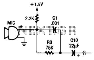
This circuit is suitable for using an electret microphone for various applications. A 1.5-V battery is utilized. CI and R3 provide treble boost and bass cut; they can be eliminated if desired. The described circuit employs an electret microphone, which...
The circuit operates by detecting a clapping sound through a piezoelectric ceramic sensor, which converts the sound into an electrical signal. This signal is then amplified by the transistor VT1 and fed through a coupling capacitor C1 to the...