
High Speed NiCd Charger for R/C
The described charging system is designed to efficiently handle NiCd (Nickel-Cadmium) battery packs, specifically targeting configurations such as the 7-cell RC2000 and the 8-cell RC2400 or CP2400SCR. The charging process is optimized to complete within 14 to 17 minutes, respectively, which is crucial for applications requiring quick turnaround times.
During the charging process, two primary phenomena influence the thermal behavior of the NiCd cells. First, the internal resistance of the cell generates heat as the charging current flows through it, a phenomenon quantified by the I²R losses, where 'I' represents the charging current and 'R' represents the internal resistance. This heat generation is an essential factor to monitor, as excessive heat can lead to cell degradation or failure.
Simultaneously, the electrochemical process occurring within the NiCd cells is endothermic. This means that the chemical reaction involved in charging absorbs heat, acting as a cooling mechanism during the initial phase of charging. However, once the cell reaches full charge, this endothermic reaction ceases, and any continued application of current can lead to an increase in temperature. The implications of this are significant; if the charging current remains constant, the cell will begin to heat up due to the I²R losses without the counteracting cooling effect of the endothermic reaction.
For example, if a charging current of 10 Amps is sustained, the resultant heat buildup can be considerable, necessitating careful thermal management strategies to prevent overheating. It is essential to incorporate temperature monitoring and current regulation features in the charging circuit design to ensure that the cells are charged safely and efficiently, prolonging their operational lifespan and maintaining performance.
Overall, the charging system must balance the rapid charging capabilities with the thermal management of the cells to ensure optimal performance and safety during operation.It can safely charge a 7-cell RC2000 pack in about 14 minutes, and an RC2400 or CP2400SCR pack in about 17 minutes. As a NiCd cell is being charged, two things happen which affect its temperature. Due to resistive losses within the cell, some of the charging current is converted to heat (I2R losses).
At the same time, the chemical reaction that takes place during NiCd charging absorbs heat (i.e. it`s an endothermic reaction). Once a cell is fully charged, the endothermic chemical reaction stops. This means that continued charging current, no matter how low, will cause the cell to heat up. Higher currents will heat the cell up faster. At 10 Amps for example, the cell will heat 🔗 External reference
Related Circuits
This circuit allows appliances to remain connected to an inverter. While it does not influence weather conditions, it ensures that batteries are safely charged even during periods of generation shortfall. This device is referred to as the Grid Charger...
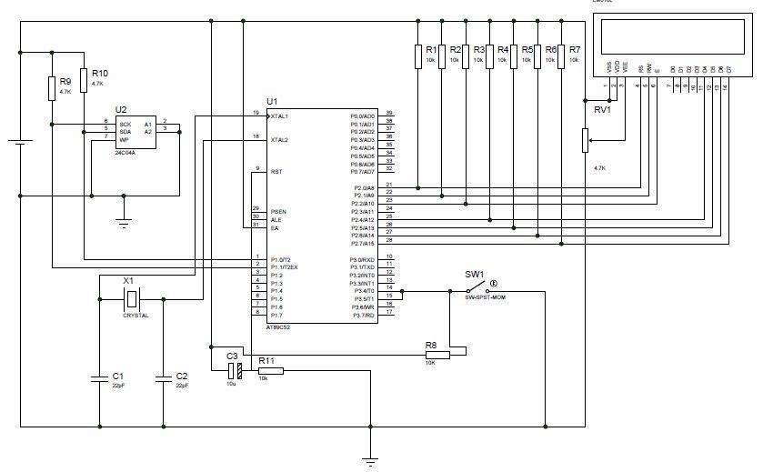
This project involves creating a digital speedometer and odometer using the AT89S52 microcontroller. Testing has been conducted using the Proteus (ISIS) simulator, and the design is functioning correctly. The digital speedometer and odometer project utilizes the AT89S52 microcontroller, which is...
This simple, one-transistor amplifier provides a voltage gain of over 1000 (60 dB) for an active aerial impedance crystal earphone. The gain is achieved by replacing the standard load resistor with a constant-current diode that supplies 1/2 mA while...
A simple battery charging circuit is designed using a flyback converter current-limited power supply to charge lead-acid batteries. This circuit is developed by Maxim Integrated. The described battery charging circuit utilizes a flyback converter topology, which is well-suited for applications...
A pulse width modulator (PWM) is a device that may be used as an efficient light dimmer or DC motor speed controller. The circuit described here is for a general purpose device that can control DC devices which draw...
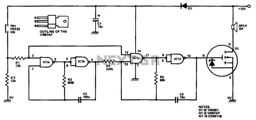
ICla and IClb are configured as a slow astable multivibrator, while IClc and ICld are arranged as a fast astable multivibrator. The output from the slow astable modulates the frequency of the fast astable, and the output from the...