
PWM Motor Speed Controller
The pulse width modulation (PWM) circuit operates by generating a square wave signal whose duty cycle can be adjusted to control the amount of power delivered to a load. The circuit is typically designed to accommodate DC devices that require a current draw of several amps, making it suitable for applications such as dimming lights or controlling the speed of small DC motors.
The core of the PWM circuit often includes a timer or microcontroller that produces the square wave output. The frequency of this square wave is usually fixed, while the duty cycle—the ratio of the time the signal is high (on) to the total period of the signal—can be varied. By changing the duty cycle, the average voltage and current supplied to the load can be adjusted, effectively controlling the brightness of a light or the speed of a motor.
For operation in 12 or 24 Volt systems, the circuit may incorporate a few minor modifications in the wiring configuration, allowing for versatility in application. The output stage typically consists of a transistor or MOSFET capable of handling the required load current, ensuring efficient switching with minimal heat generation.
In practical applications, such as automotive lighting or cooling fans, the PWM circuit provides a smooth and efficient control method compared to traditional resistive dimming or speed control methods. By using PWM, the circuit minimizes power loss and enhances the operational lifespan of the components involved. Overall, the PWM circuit serves as a reliable solution for various DC power management needs.A pulse width modulator (PWM) is a device that may be used as an efficient light dimmer or DC motor speed controller. The circuit described here is for a general purpose device that can control DC devices which draw up to a few amps of current.
The circuit may be used in either 12 or 24 Volt systems with only a few minor wiring changes. This device has been used to control the brightness of an automotive tail lamp and as a motor speed control for small DC fans of the type used in computer power supplies. A PWM circuit works by making a square wave with a variable on-to-off ratio, the average on time may be varied from 0 to 100 percent. In this manner, a variable amount of power is transferred to the load. The main advantage of a PWM circuit over a resisti 🔗 External reference
Related Circuits
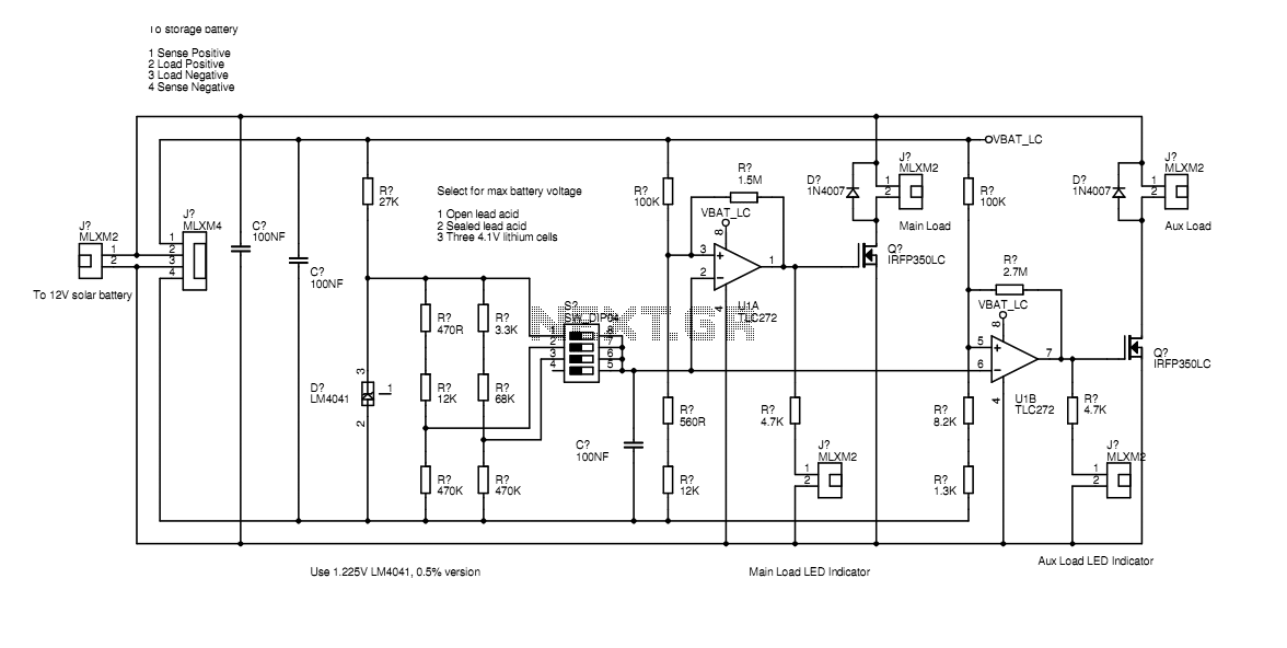
In the actual device the transistors are bolted to the aluminium case. The schematic diagram shown here represents how the circuit would be built if all components were on-board. Separate paths for load current and voltage sensing allow the...
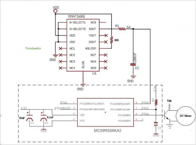
The MIC2199 is a synchronous buck switching regulator controller. It features an all N-Channel synchronous architecture and powerful output drivers that enable a maximum output current capability of 20A. The device operates with an input voltage range of 4.5V...
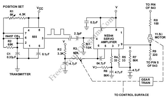
This is a servo system controller circuit designed for remote control of a servo motor. The circuit utilizes a 555 timer and requires only six additional components. The servo system controller circuit operates by generating a pulse-width modulation (PWM) signal,...
This device is a two-line audio EMI filter array designed for speaker applications. It provides greater than 35 dB attenuation at frequencies ranging from 800 MHz to 3.0 GHz. Additionally, this device offers ESD protection by clamping transients from...
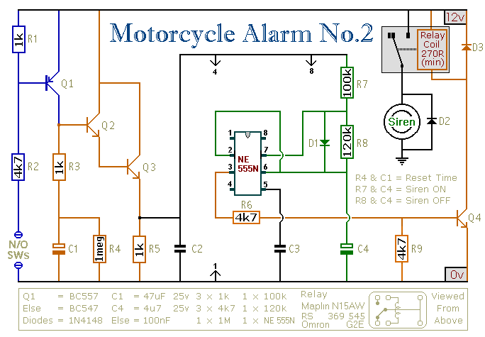
This circuit provides an intermittent siren output with an automatic reset function. It can be manually activated using a key switch or a concealed switch, and it can also be configured to engage automatically when the ignition is turned...

The circuit described here is for a general purpose device that can control DC devices which draw up to a few amps of current. The circuit may be used in either 12 or 24 Volt systems with only a...