
High speed warning device

The circuit consists of several key components that work together to monitor and regulate engine speed. The first component, A1, functions as an amplifier and regulator, enhancing the signal received from the spark coil. This is crucial for ensuring that the subsequent components receive a stable and strong signal, which is necessary for accurate processing.
Following A1, A2 operates as a frequency-to-voltage converter. It takes the frequency signal derived from the engine's RPM and converts it into a corresponding voltage level. This output voltage is directly proportional to the engine's RPM, allowing for easy measurement and comparison in the next stage of the circuit.
A3 serves as a comparator. It compares the voltage output from A2 with a predetermined reference voltage. When the engine RPM reaches a specific threshold, A3 activates an output transistor. This action can trigger various responses in the system, such as activating a warning light or engaging a control mechanism, depending on the overall design of the circuit.
Additionally, A4 is employed to generate an audible tone when the engine exceeds the set speed. This amplifier is designed to produce a sound signal that alerts the operator of the engine's over-speed condition, enhancing safety and operational awareness.
Overall, the described circuit provides a comprehensive solution for monitoring engine RPM, ensuring that the engine operates within safe limits while providing audible alerts for over-speed conditions. Each component plays a vital role in the system, contributing to its overall functionality and reliability.A1 amplifies and regulates the signal from the spark coil. A2 converts frequency to voltage so that its output is a voltage proportional to engine rpm. A3 compares the tachometer voltage with the reference voltage and turns on the output transistor at the set speed Amplifier A4 is used to generate an audible tone whenever the set speed is exceeded.
Related Circuits
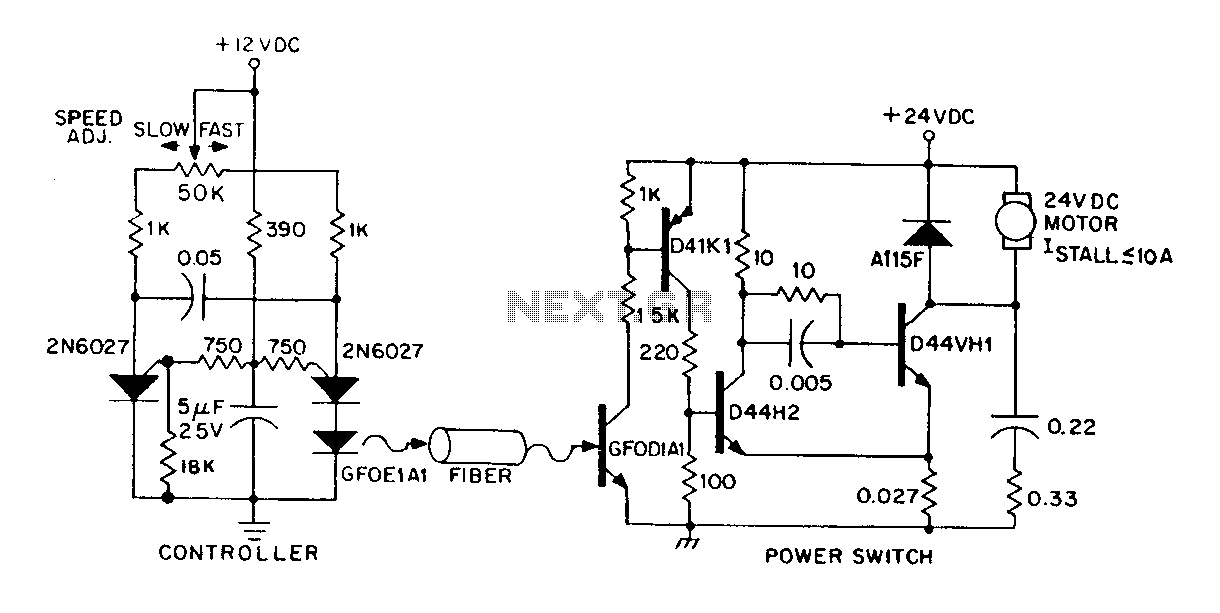
A DC power supply can be controlled through an optical fiber. The circuit includes a small DC motor (1/12 hp) that offers an isolated speed control channel. The control logic operates as an independent module, consuming 300 mW of...
A high-quality intercom system that can also be utilized for room monitoring. The intercom system described is designed to provide clear and reliable communication between different rooms or areas within a building. It features high-fidelity audio components that ensure minimal...
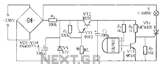
The H1.9811 single-channel flash control integrated circuit from Wuxi Love Core Microelectronics Co., Ltd. is designed for controlling flashing warning lights in road barricades. It features an integrated internal RC oscillator, frequency divider, output buffer amplifier, shaping circuit, and...
This high voltage converter circuit operates from a 30-volt power supply and can output a voltage ranging from 0 to 3 kV in version 1 or from 0 to 10 kV in version 2. The high voltage converter circuit is...
This circuit is designed to demonstrate high-frequency high voltage, capable of producing approximately 30 kV, depending on the transformer utilized. It is cost-effective and simple to construct, primarily using a standard TV flyback transformer. The circuit can power lasers,...
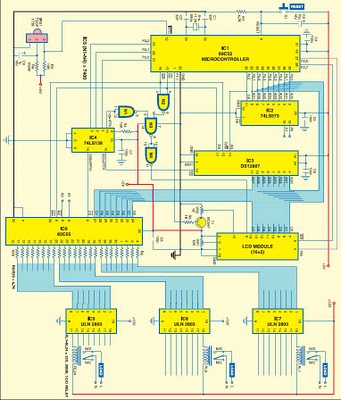
This project is based on the Atmel AT89C52 microcontroller and the Dallas real-time clock (RTC) chip DS12887. It can control and remotely program the switching operations of 24 electrically operated devices, allowing them to be turned on or off...