
By DC variable speed motor control circuit diagram of an optical fiber
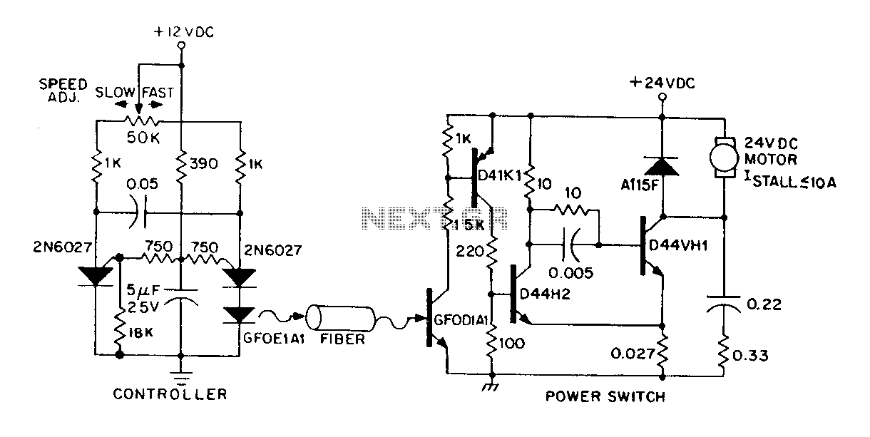
The described circuit integrates a DC power supply with optical fiber control capabilities, enhancing the versatility of motor speed regulation. The small DC motor, rated at 1/12 horsepower, serves as the actuator, while the optical fiber communication allows for remote operation, minimizing electrical noise and interference typically associated with traditional wiring methods.
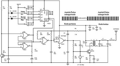
The independent control module operates at a nominal voltage of 12V and consumes 300 mW, making it suitable for battery operation. This characteristic is essential for applications requiring portability or in environments where conventional power sources are unavailable. The inclusion of an infrared pulse duty cycle feature enables precise control over the motor's speed, with the frequency set at 160 Hz, which allows for rapid adjustments in response to varying operational demands.
The speed control is facilitated through a potentiometer, which alters the input to the control module, thereby adjusting the motor's performance. The programmable unijunction multivibrator (GFOE1A1) is a key component in this system, capable of generating pulses with a duty cycle adjustable from 1% to 99%. This flexibility allows for fine-tuning of the motor speed, catering to specific application requirements.
In summary, this circuit design presents a robust solution for controlling a DC motor via optical fiber, emphasizing efficiency, modularity, and programmability. The combination of these elements positions this system as an effective choice for modern applications requiring reliable and precise motor control.DC power supply can also be controlled via an optical fiber. The circuit is a small DC motor ( 1/12hp) providing an insulating speed control channel. The control logic is an in dependent module, at the time of 12V consumes 300mW of power, it can be powered by a battery. The control module can provide infrared pulse duty cycle and speed of the speed control potentiometer location 160Hz decision. Programmable unijunction multivibrator duty cycle in the range of 1% to 99% to provide a pulse of about 10mA is GFOE1A1.
Related Circuits
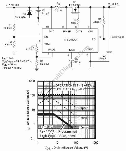
This is a positive high-voltage hot swap controller circuit with a power limiter. This circuit utilizes the TPS2491 or TPS2490, as both of them have specific features. The positive high-voltage hot swap controller circuit is designed to safely connect and...
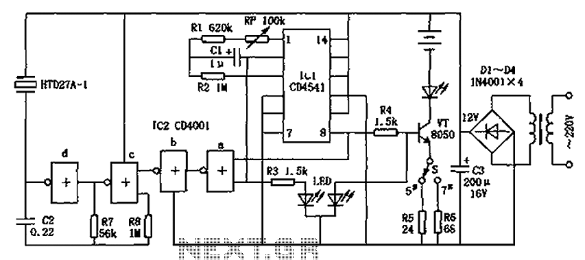
The CD4001/CD4541 nickel-cadmium battery automatic charger circuit is illustrated in the figure. This circuit is designed for charging up to seven rechargeable nickel-cadmium batteries. It features automatic charging with constant current characteristics. Once powered, the circuit activates an internal...
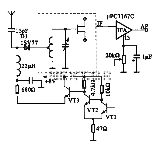
This circuit illustrates an FM modulator with a strong and weak signal switching mechanism. The circuit diagram 3-14 (a) depicts mechanical switches, including a worker selector switch that allows for signal strength selection. Figure 3-14 (b) demonstrates the implementation...
The following circuit illustrates a schematic diagram for a remote control toy car. Features: it does not interfere with the performance of the original design. The remote control toy car circuit typically consists of several key components that enable wireless...
The TX05C-R infrared surveillance alarm circuit is designed for monitoring walls, windows, doors, and various restricted areas. When an intrusion occurs, the alarm activates to enhance security. The circuit comprises a transmitter module, a receiver module, a time-base circuit,...
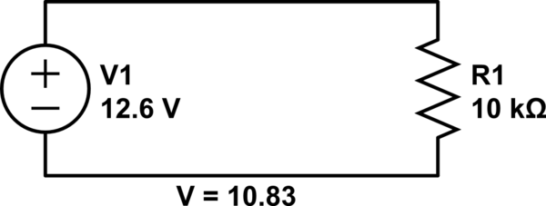
Connect a 12V fan to this circuit that consumes 70mA (0.07A), ensuring the circuit can supply at least that amount of current. There appears to be a misunderstanding regarding the analysis. The voltage drop across the resistor equals the...