
Solid State Tesla Coil/High Voltage Generator
The circuit uses a high voltage flyback transformer, which can be salvaged from an old television or purchased from suppliers such as Fair Radio Sales. When selecting a transformer, it is advisable to choose a large and robust model, preferably from older tube televisions, ensuring that it does not have a built-in rectifier.
The first step involves rewinding the transformer's primary winding. This requires the careful removal of the old primary winding without damaging the high voltage secondary. If the transformer has all windings encased in plastic, it is recommended to find another transformer. The new primary winding consists of 5 turns of 18 AWG wire, with a center tap created by twisting a loop, followed by an additional 5 turns. This configuration is designated as winding C-D. Subsequently, 2 turns of 22 AWG wire should be wound, twisted into a loop, and followed by 2 more turns, creating winding A-B.
Transistors Q1 and Q2 must be adequately cooled with a large heatsink, as they tend to run hot during operation. After a few minutes of running, it should still be possible to touch the transistors without being burned. Resistors R1 and R2 will also generate heat. If arcing occurs on the exposed transformer leads, it is advisable to select a lower voltage for transformer T1. When powering the circuit with a power supply, reducing the voltage can mitigate this issue.
The first illustration shows the high voltage generator without the voltage multiplier, highlighting the intensity of the arc produced. The second illustration depicts the generator with a voltage multiplier installed, demonstrating a significantly brighter arc. Safety precautions are crucial when operating this circuit. It is recommended to stand on an insulated surface, such as a pie plate placed on a plastic bucket, which is connected to the high voltage generator and charged to approximately 40,000 V. It is essential to have another person operate the high voltage generator and to avoid touching any components while charged. All items to be handled should be positioned on the bucket and kept away from grounded objects. Additionally, any jewelry, such as watches, should be removed prior to operation.
This circuit serves as an educational tool for exploring high voltage phenomena, while emphasizing the importance of safety and proper handling practices.This is a fun and useful circuit for demonstrating high frequency high voltge. It can produce up to about 30KV, depending on the transformer used. It is cheap and easy to make, thanks to the standard TV flyback transformer used. It can power LASERS (although I have never tried), demonstrate St. Elmo`s fire, and even cause a fluorescent bulb to ligh t from as much as 2 feet away. 1. T2 is a high voltage flyback transformer salvaged from an old TV, or ordered from Fair Radio Sales (see Where To Get Parts). Look for the biggest, most intimidating transformer you can find. Old tube TV`s are a good place to look. The transformer should not have a rectifier built in. 2. You will need to rewind the transformer`s primary. First, remove the old primary, being careful not to damage the high voltage secondary. If the transformer is wound with all windings incased in plastic, use another transformer. Second, wind on 5 turns of 18 AWG wire, twist a loop (center tap), and then wind on 5 more turns. This becomes winding C-D. Now, wind on 2 turns of 22 AWG wire, twist a loop, and wind on 2 more turns. This becomes winding A-B. 3. Q1 and Q2 will run HOT if not used with a large heatsink. After the circuit has been running for a minute or two, you should still be able to put your finger on the transistors without being burnt.
Also, R1 and R2 will run hot. 4. If you experience arcing on the exposed transformer leads, select a lower voltage for T1. If you are powering the circuit with a power supply (see Power Supply ), just crank down the voltage. The first picture is the high voltage generator without the voltage multiplier. Notice how hot the arc looks. The second picture is the high voltage generator with a voltage multiplier installed. Notice how much brighter the arc is. The above pictures of myself were taken with me standing on an pie plate that was resting on the top of a plastic bucket.
The pie plate was connected to the high voltage generator and charged to about 40, 000V. If you do this, be sure to have someone else turn on and off the high voltage generator. Also, don`t touch anything when you are charged. Have everything you are going to hold/play with already sitting on the bucket and away from grounded objects. Remember to take off your watch. 🔗 External reference
Related Circuits
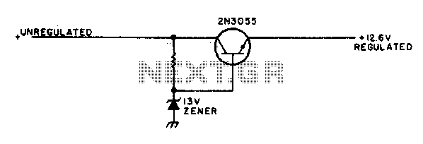
This simple mobile voltage regulator circuit may save your two-meter or CB transceiver if the voltage regulator fails. The 2N3055 should be heat-sinked if the current drawn by the rig exceeds 2 A during transmission. This circuit will do...
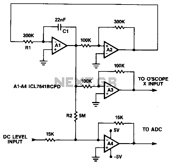
This circuit generates a symmetrical 10 mV peak-to-peak triangle waveform that is summed with a DC level and connected to the analog input for noise and DNL testing. The DC level input offsets the triangle waveform over the input...
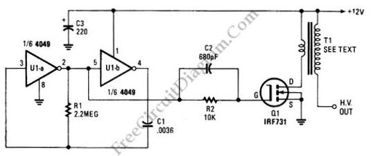
The schematic diagram below illustrates a high voltage generator circuit. This circuit employs a 4049 hex inverter functioning as an oscillator, with the option to utilize an ignition transformer from an automotive engine. A flyback transformer may also be...
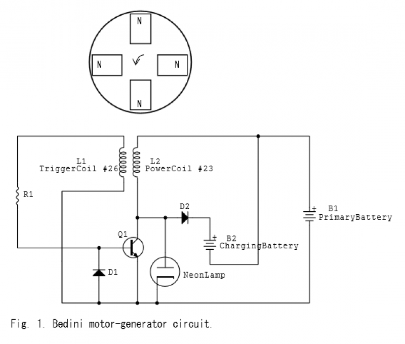
When the magnet approaches, the magnetic flux within the bifilar coil increases. An opposing magnetic flux is generated by the coil, resulting in an electromotive force (EMF) across inductors L1 and L2. The EMF across L1 applies a positive...
A sawtooth wave generator utilizing the NE555 timer and the uA741 operational amplifier. The NE555 is configured as a square wave generator, while the uA741 is set up as an integrator. The circuit diagram and working theory are included. The...
In the miniature high-voltage DC generator, the circuit receives input from a 12 V DC power supply, which is amplified to produce a 10,000 V DC output. This process induces a pulsating signal of opposite polarity in the secondary...