
High-Voltage Generator with HEX FET
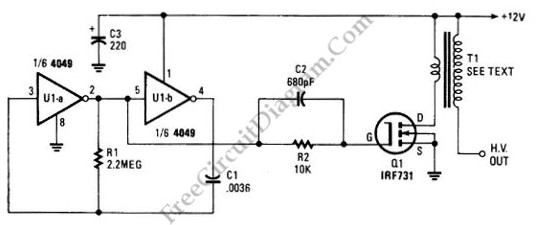
The high voltage generator circuit is designed to convert low voltage input into a high voltage output using a combination of oscillation and transformer action. The 4049 hex inverter serves as the core oscillator, producing a square wave output that is essential for driving the transformer. The choice of the ignition transformer or a flyback transformer is critical, as both are capable of stepping up the voltage significantly.
The IRF731 HEX FET is utilized as a switching element in this circuit. It is crucial to ensure that the FET operates within its specified limits, particularly regarding voltage and current ratings. The requirement for a heatsink indicates that the FET will dissipate heat during operation, necessitating adequate thermal management to maintain performance and reliability.
In practical applications, the circuit can be used for generating high voltages for various purposes, including ignition systems, gas tube lighting, or other applications requiring high voltage pulses. Care should be taken to design the circuit layout to minimize parasitic inductance and capacitance, which can affect performance. Additionally, safety precautions must be observed when working with high voltages to prevent electrical hazards.
Overall, this high voltage generator circuit provides a compact and efficient solution for applications requiring high voltage outputs, leveraging the capabilities of the 4049 hex inverter and the selected transformer type.The schematic diagram below show a circuit of high voltage generator. This circuit uses a 4049 hex inverter as an oscillator, and you can use ignition transformer from automotive engine. A fly-back transformer is possibly usable too. The 4049 will drive the IRF731 HEX FET. The Q1 must be heatsinked. Here is the schematic diagram of the circuit: (source: free.. 🔗 External reference
Related Circuits
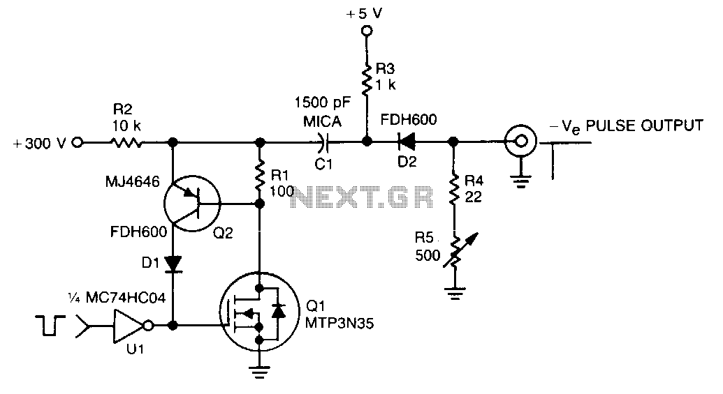
In this TMOS pulser, a negative-going pulse is applied to U1, a high-speed CMOS buffer, which directly drives the gate of Q1, an MTP3N35. If only a 100-V pulse is required, the MTA6N10 can be used. The pulse output...

Noise level measured into 75ohm 3.1kHz BW using Siemens D2006 level meter: -80dBU (77.5mV) from zero to 1MHz and drops 3dB on 17MHz. Decrease the first coupling capacitor (68nF) to 10nF to increase the lower limit to 50kHz. The...

This is a 2W RF amplifier circuit built with the power MOSFET LF2810A. The schematic of the microstrip single-stage RF amplifier is shown in Figure A. The amplifier utilizes the M/A-Com LF2810A MOSFET, which is rated for a power...
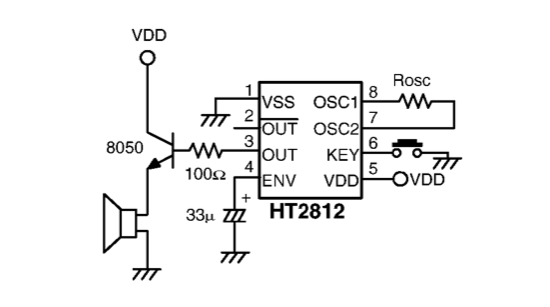
A sound generator is needed for a room monitoring system. Suggestions for an electronic design are requested, as the HT2810 or similar components are not preferred. The sound generator circuit for a room monitoring system can be designed using a...
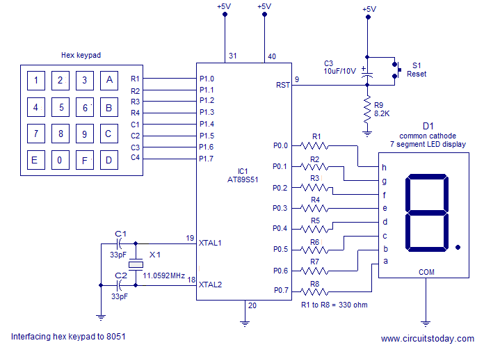
Interfacing a hex keypad to an 8051 microcontroller. The AT89S51 is utilized in this setup. A circuit diagram and assembly language program are included. A testing video is also provided. The interfacing of a hex keypad with the AT89S51 microcontroller...
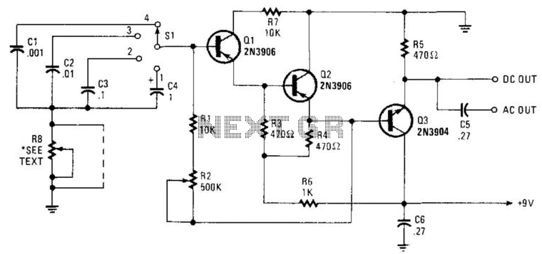
Seven narrow pulses ranging from 2 Hz to 50 kHz are generated by this circuit. Capacitors C1 through C4 provide frequency ranges in decode steps. Resistors R1 and R2 regulate the charging time of capacitors C1 through C4. R2...
Warning: include(partials/cookie-banner.php): Failed to open stream: Permission denied in /var/www/html/nextgr/view-circuit.php on line 713
Warning: include(): Failed opening 'partials/cookie-banner.php' for inclusion (include_path='.:/usr/share/php') in /var/www/html/nextgr/view-circuit.php on line 713