
2W RF Amplifier with MOSFET LF2810A

The 2W RF amplifier circuit is designed to enhance the power level of radio frequency signals, making it suitable for various applications in communication systems. The LF2810A MOSFET is a key component, chosen for its high efficiency and capability to operate at microwave frequencies. This device features a low gate-source capacitance, which allows for faster switching speeds, making it ideal for RF amplification.
The circuit typically includes a matching network at the input and output stages to ensure maximum power transfer and minimize reflections. The input matching network is designed to match the source impedance to the gate of the MOSFET, while the output matching network optimizes the load impedance for the drain. This configuration helps to achieve a high gain and a low noise figure, which are critical parameters in RF applications.
Power supply decoupling capacitors are often included in the design to stabilize the voltage supplied to the MOSFET and to filter out any high-frequency noise that may affect the amplifier's performance. Additionally, thermal management components, such as heat sinks, may be employed to dissipate heat generated during operation, ensuring reliable performance over extended periods.
The overall layout of the microstrip circuit is crucial for maintaining performance at RF frequencies. Careful consideration must be given to trace widths, lengths, and the dielectric material used in the substrate to minimize losses and maintain signal integrity. Proper grounding techniques are also essential to prevent unwanted interference and ensure a stable operating environment for the amplifier.
In summary, this 2W RF amplifier circuit utilizing the LF2810A MOSFET is a well-engineered solution for enhancing RF signal power, with a focus on efficiency, performance, and reliability in communication systems.This is a 2W RF amplifier circuit build with power MOSFET LF2810A. Figure A Figure A is the schematic of the microstrip single stage RF amplifier. The amplifier is based on the M/A-Com LF2810A MOSFET. The transistor is actually a watt, 2.. 🔗 External reference
Related Circuits
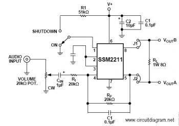
The SSM22111 is a high-performance audio amplifier that delivers 1 W RMS of low distortion audio power into a bridge-connected 8-ohm speaker load (or 1.5 W RMS into a 4-ohm load). The SSM2211 operates over a wide temperature range...
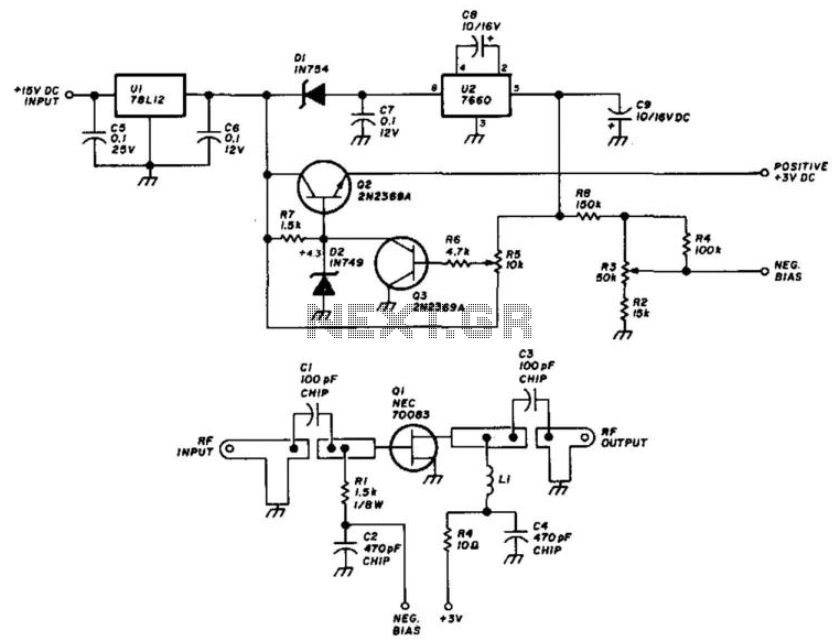
Using an NEC70083, this 1296-MHz amplifier provides approximately 17 dB of gain with a noise figure ranging from 1 to 1.5 dB. It is built on a G-10 epoxy fiberglass printed circuit board (PCB). Adhering to the specified layout...
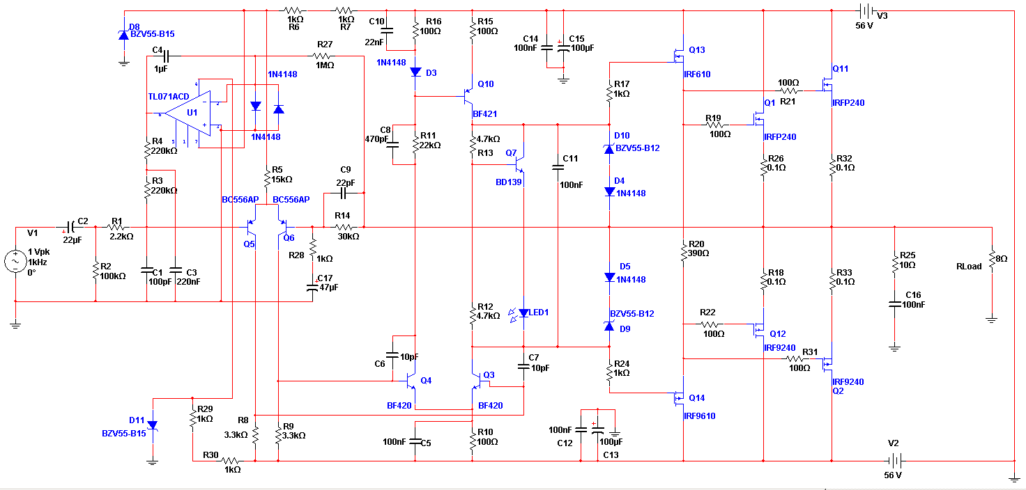
The Apex amplifier has a corrected schematic that includes variations of the resistor R14 with different values (22k, 30k, 56k) and different power supply configurations. The Apex amplifier circuit is designed to deliver high-fidelity audio amplification. The schematic incorporates a...
The common mode signal rejection ratio is influenced by the input transformer, which should either be a commercially available or a well-balanced homemade transformer. It is important to note that as frequency increases, the balance may decrease. The transmission...
Magnetic pickups in musical instruments exhibit a relatively high output impedance, which can lead to a decrease in treble response when connected through long cable runs or to equipment with low input impedance. This preamplifier addresses these challenges by...
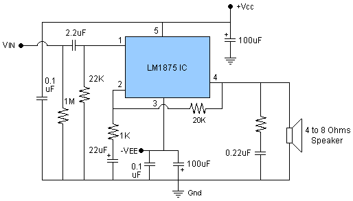
The circuit presented is a 20W audio amplifier utilizing the LM1875 integrated circuit (IC). The LM1875 is a high-quality, low-distortion audio amplifier IC rated for 20 watts, available in a TO-220 package. This IC includes several built-in features such...