
High-Voltage Pulse Generator

The circuit design includes a free-running variable multivibrator utilizing transistors Q1 and Q2, which drive a Darlington power amplifier, Q3. This configuration allows for the modulation of the primary current to the ignition coil, generating the desired high-voltage pulses. The multivibrator's frequency control enables the user to adjust the pulse rate, thereby tailoring the output to specific experimental needs. Additionally, the incorporation of safety features, such as the current-limiting lamp and the grounding of the power supply, enhances the overall reliability and safety of the circuit. The circuit layout should be carefully designed to minimize the risk of unintended contact with high-voltage components, reinforcing the importance of adhering to safety protocols during operation. Proper insulation and housing for the high-voltage sections are also critical to prevent accidental contact and ensure safe operation. Overall, this high-voltage generator project presents a versatile tool for various applications while emphasizing the importance of safety and proper circuit design.If you`ve ever wanted a high-voltage generator to create neat lightning effects, perform Kirlian photography experiments or play with neon lights, then this one is for you!. " We will describe a laboratory pulse generator using an auto-ignition coil and capable of delivering a train of pulses up to 30, 000 volts.
With a couple of minor circuit and construction variations, the project is suitable for use as an electric-fence charger, operating at a lower voltage, but capable of much higher output current. Applications for a high-voltage spike are numerous: electromagnetic and radio-frequency interference (RFI) studies, electrostatic-discharge simulation; investigation of insulation breakdown; flammability experiments; strobe effects; etc.
A DC power supply or battery is required, and pulse potential may be varied simply by changing the supply voltage. With a 12. 6-volt input, the ignition-coil model delivers its maximum pulse, but a unique multivibrator-driver circuit makes operation possible down to a supply voltage as low as 1.
5 volts, yielding an output pulse of only a few hundred volts. Its pulse frequency is set by a front-panel control, with a range from about 0. 3Hz to 20 Hz. An ignition coil, however, is not well adapted to the fence-charger application since its output resistance is so high: typically 10, 000 ohms. Thus its output pulse is strongly dependent on loading. With a short fence, long sparks might be struck at risk of igniting brush; while on the other hand, with a long fence, shunting by weeds or by dirt and moisture may reduce its output voltage below and effective value.
Hence for the fence-charger version the rate prf control must be omitted fro reason of safety. No-load output of the fence-charger option is typically 4 Kv pk (kilovolts peak), or about half that valuer when connected to a 1-mile fence. A car battery powers the fence-charger model for about four months before recharging is needed (at recommended pulsing rate of 20 pulses/minute).
While a single jolt from an ignition coil is itself rarely traumatic, the resulting-reflex muscle contraction could have unfortunate consequences. If a continuous train of pulses causes you to involuntarily grasp the high-voltage conductor, for instance, you might not be able to let go.
On the other hand, if proper return circuit is not provided, an equally distressing shock could be had by contact with the primary circuit. Because the ignition coil is an autotransformer, the return circuit for the high-voltage pulse includes the power leads.
Therefore, one side of the power supply should, if possible, be Earth grounded. That precaution besides shock by contact with the power leads, also precludes arcing within the power supply itself as the high-voltage pulse seeks the shortest return path. Applying that reasoning to the fence-charger option, we can see why a fixed pulse rate is specified, as there is a strong likelihood of accidental human contact with the fence wire; a rate of 60 pulses per minute or less being considered safe.
Also, since there is a good chance of personal contract with the power leads, a good ground connection is essential, as with any electric-fence system. For maximum safety, we recommend a battery supply for the fence-charger system. If you should happen to reverse the power-supply lease to either project, the current-limitation lamp, a large automotive bulb easily seen in the photos, lights brightly to warn you.
However, the equipments must not be allowed to remain in this condition for more than a few seconds. Even if you never expect to make this mistake, the lamp should be included because it limits excessive surge currents that could otherwise occur under some operating conditions and which could blow the power transistor. As shown in Fig. 1, free-running variable multivibrator Q1 and Q2 drive Darlington power amplifier Q3, which makes and breaks the primary current to c
🔗 External reference
Related Circuits
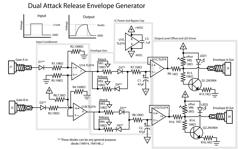
This is a dual Attack/Release envelope generator that has been added to the Modular Benjolin design. While not essential, it provides enjoyable functionality, particularly when used alongside the modular rungle bit output mod. The circuit is straightforward, making it...
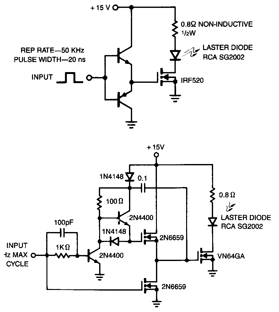
The laser diode pulser is a simple drive circuit capable of driving the laser diode with 10 A, 20 ns pulses. For a 0.1% duty cycle, the repetition rate will be 50 kHz. A complementary emitter follower is used...
Pulse Generator kit will generate a frequency in KHz which can form a good test gear project. This kit is based on the classic LM555 timer IC. Input - 12 VDC Max @ 40 mA. Range - jumper selectable...

The circuit produces a pleasing and accurate imitation of sound, making it suitable for sound effects such as doorbells. It generates a two-tone effect that closely resembles the sound of a cuckoo. This circuit is designed to create a two-tone...
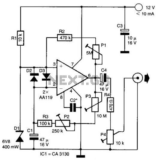
This circuit generates noise pulses suitable for test purposes. A Zener diode serves as the noise source. IC1 functions as a relaxation oscillator. P1 determines the noise bandwidth, while P2 and P3 control the noise amplification. The current consumption...

This circuit design generates a stable 1 kHz sine wave using an inverted Wien bridge configuration with components C1-R3 and C2-R4. It offers a variable output, low distortion, and low output impedance to ensure good overload capability. The circuit...