
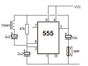
555 timer Pulse generator
The Pulse Generator kit utilizes the LM555 timer integrated circuit, a versatile and widely used component in timing applications. This particular kit is designed to generate pulse signals in the frequency range of 1 Hz to 180 KHz, making it suitable for a variety of testing and experimentation purposes. The frequency output can be easily adjusted using jumper settings, allowing users to select from predefined ranges or tune it to specific values as needed.
The power supply requirement for the kit is a maximum of 12 VDC with a current draw of 40 mA, ensuring compatibility with standard power sources. The inclusion of a Power-On LED indicator provides a visual confirmation that the circuit is powered and operational, enhancing usability during testing and development.
For ease of integration into various projects, the kit features terminal pins that facilitate straightforward connections to other components or test equipment. Additionally, the PCB is equipped with four mounting holes, each measuring 3.2 mm, allowing for secure installation in enclosures or on breadboards.
The compact dimensions of the printed circuit board (PCB) at 40 mm x 47 mm make it suitable for use in space-constrained applications. Overall, the Pulse Generator kit represents a practical solution for engineers and hobbyists looking to create reliable pulse signals for testing and experimentation in electronic projects.Pulse Generator kit will generate a frequency in KHz which can form a good test gear project. This kit is based on the classic LM555 timer IC. Input - 12 VDC Max @ 40 mA. Range - jumper selectable and preset tunable range of 1 Hz to 180 KHz. Power-On LED indicator. Terminal pins for easy connection. Four mounting holes of 3.2 mm each. PCB dimensions 40 mm x 47 mm 🔗 External reference
Related Circuits
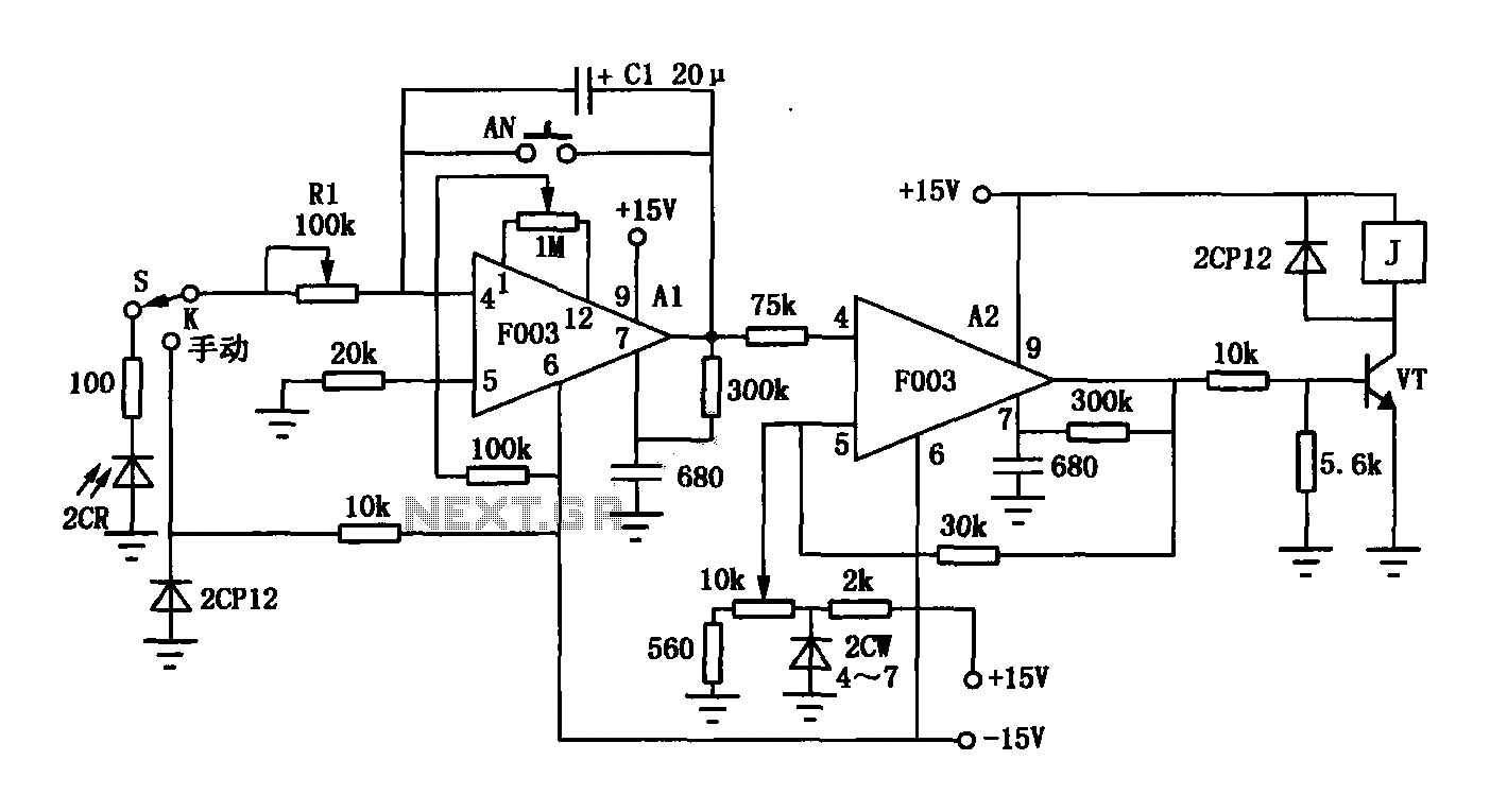
The F003 circuit is a versatile photographic component that functions as an operational amplifier amplifying automatic timer circuit. The operational amplifier A1 serves as an integrator, while operational amplifier A2 is configured as a comparator. A 2CR silicon photocell...
This metal detector electronic project schematic circuit is designed using a simple 555 timer integrated circuit. The schematic circuit requires a few external electronic components. The metal detector circuit utilizes the 555 timer IC in astable mode to generate a...
This document outlines a basic circuit designed to power high impedance, high voltage, low current devices such as electroluminescent (EL) backlights and fluorescent tubes. The project originated from the need for a simple yet flexible inverter circuit for an...

This design outlines a fire alarm circuit that utilizes a light-dependent resistor (LDR) and a lamp to detect fire. The alarm is activated by sensing the smoke produced during a fire. When smoke is present, it obstructs light from...
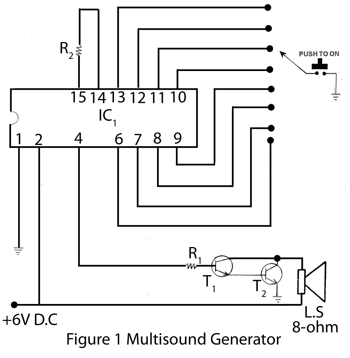
The multisound generator is an intriguing project within the alarm system series. This generator produces eight different types of sounds, and it includes a circuit diagram for various electronic projects. The multisound generator circuit is designed to create a variety...
This DC voltage doubler circuit generates a voltage that is double its supply voltage. It is beneficial when a higher voltage level is required from a single power source. The DC voltage doubler circuit typically employs a combination of capacitors...