
High voltage stable power supply
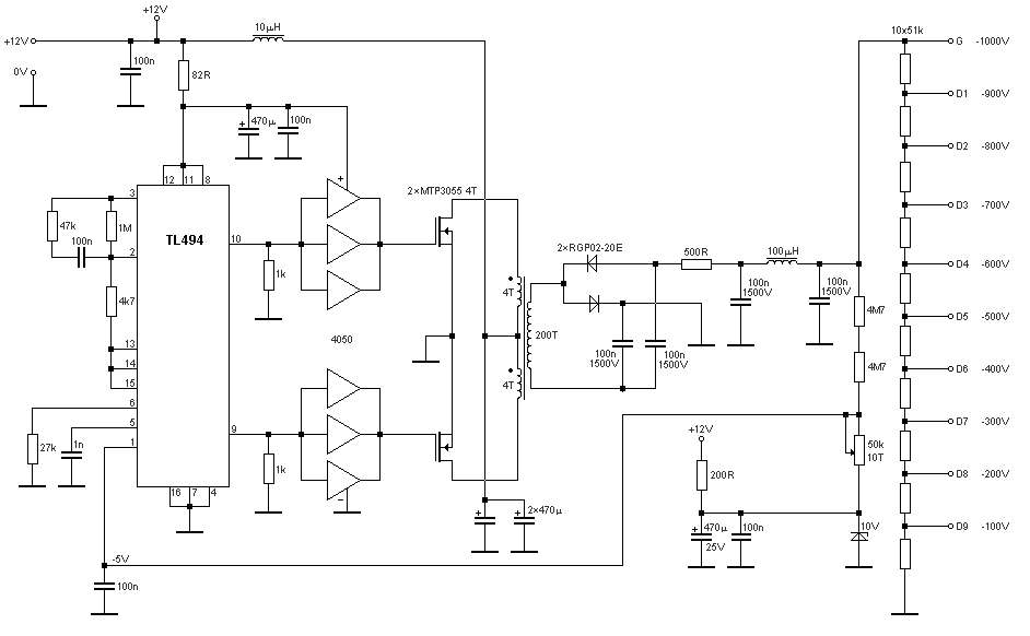
The schematic for the stable power supply is essential for applications requiring high voltage precision and reliability. The TL494 PWM controller is a central component, known for its versatility in regulating power supplies. It operates by adjusting the duty cycle of the output signal, which directly influences the voltage and current delivered to the load. The use of field-effect transistors (FETs) enhances the efficiency of the circuit, allowing for rapid switching and minimal power loss during operation.
The step-up transformer plays a critical role in increasing the voltage to the desired levels while maintaining stability across the specified temperature range. The design's robustness is evident from the experiments conducted, which confirm that the voltage source remains reliable even under varying thermal conditions. This is particularly important in high-voltage applications where temperature fluctuations can lead to significant performance variations.
The battery charger circuit is designed to provide a constant current of 5A, ensuring that the battery is charged efficiently and safely. The inclusion of diodes D1 and D3 serves to protect the circuit from reverse polarity and to manage the charging process effectively. The operational amplifier IC A1 - 142EN2 and the associated transistors are configured to regulate the charging current, preventing overcharging and extending battery life.
Furthermore, the KA2S0880 chip simplifies the construction of the power supply, integrating essential components that enhance the system's overall reliability and performance. This chip's design facilitates the development of a compact power supply unit that can deliver a stable 12V output at 2A, suitable for various applications, including powering small electronic devices and amplifiers.
In summary, the schematic diagram illustrates a sophisticated design for a stable high-voltage power supply, incorporating advanced components and configurations to ensure reliability, efficiency, and ease of implementation in various applications.The schematic diagram come from circuit: Stable Power Supply for High Voltage -100V to -1000V power supply. Go to that page to read the explanation about above power supply related circuit diagram. Stable power supply for high voltage power supply for the core of a high voltage of the PWM - Controller TL494, loaded with over 4050 followers on a pa
ir of powerful field-effect transistors, switching the primary winding of step-up transformer. Fig. 1 Highly stable source of voltage schematic Experimental studies of exemplary scheme of a highly stable source of voltage (Fig. 1) in the temperature range from -18 ° C to 50 ° C show that the temperature error of. This Battery Charger circuit allows you to charge the battery 5A constant current source that stable over time between recharging.
Charging process is accompanied by the emission of diode D1 - AL310A, and D3-AL310B. IC A1 - 142EN2, Transistors: T1, . The schematic shows the power supply capacity of 70W stereo amplifier Power converter is built on a chip KA2S0880, which includes all the necessary components to build the primary of the power supply. This chip is very stable in operation. The circuit 12 volt / 2 A switching power supply in the above scheme is not too complicated. At the output of this block provides a stable 12 V and maximum current 2A. Power supply units are quite compact and. We aim to transmit more information by carrying articles. Please send us an E-mail to wanghuali@hqew. net within 15 days if we are involved in the problems of article content, copyright or other problems.
We will delete it soon. 🔗 External reference
Related Circuits
PWM rectifier power controller power supply. Visit the page to read the explanation about the associated circuit diagram. A PWM (Pulse Width Modulation) rectifier power controller is a sophisticated electronic circuit designed to convert alternating current (AC) to direct current...
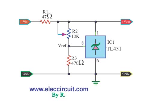
This is a simple adjustable voltage regulator power supply circuit that utilizes the integrated circuit TL431. The circuit can output a voltage range from 3V to 30V, depending on the configuration. The adjustable voltage regulator circuit employing the TL431 is...
This is a simple yet reliable device based on one of the oldest integrated voltage regulators, the LM723. The LM723 is a versatile voltage regulator that can be configured to provide a wide range of output voltages. It is capable...
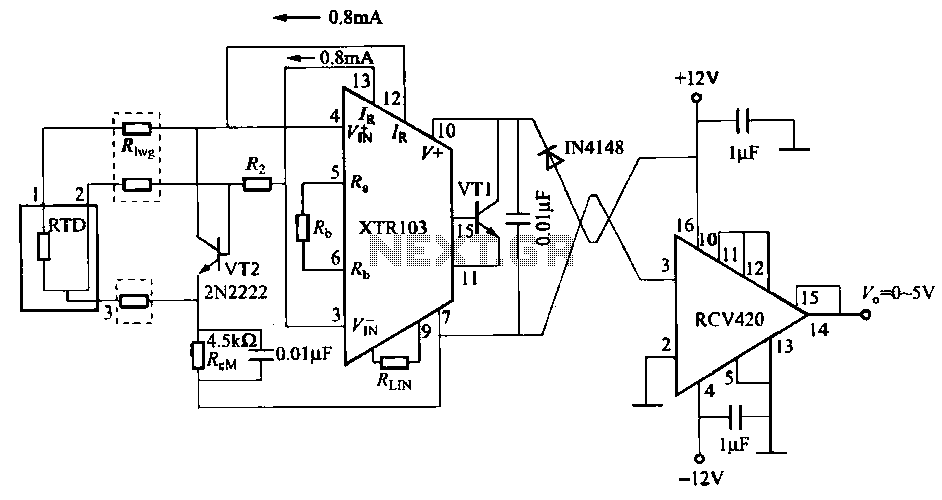
When the RTD temperature sensor is positioned far from the amplifier, the resistance of the sensor leads and their susceptibility to interference and other issues cannot be overlooked. The circuit shown in the figure addresses this problem. It utilizes...
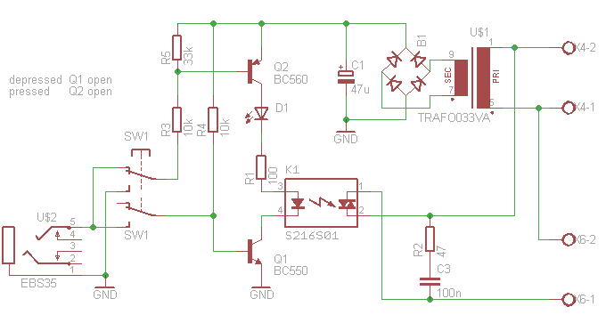
This article outlines the construction of an opto-isolated power switch designed for controlling heavy loads using logic-level signals. An opto-isolated power switch is an essential component in many electronic systems, particularly when interfacing low-voltage control circuits with high-voltage or high-current...
Construct a variable 5A, 2V to 25V regulated power supply using the LM338 adjustable regulator. A power supply schematic and parts list are provided here. The LM338 adjustable voltage regulator is a versatile component capable of providing a regulated output...