
diy opto-isolated power switch
An opto-isolated power switch is an essential component in many electronic systems, particularly when interfacing low-voltage control circuits with high-voltage or high-current loads. The primary purpose of this switch is to provide electrical isolation between the control circuit and the load, thereby protecting sensitive components from high voltage spikes and noise.
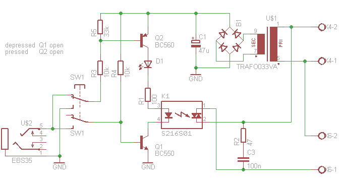
The circuit typically consists of an opto-isolator, a power transistor or relay, and necessary supporting components such as resistors and capacitors. The opto-isolator, also known as an optocoupler, contains an LED and a phototransistor. When a logic-level signal is applied to the LED, it emits light, which is detected by the phototransistor. This action allows the phototransistor to conduct, thus enabling current to flow through the load circuit.
For heavy loads, a power transistor (such as a MOSFET or BJT) or a relay can be used as the switching element. The choice between a transistor and a relay depends on the specific application requirements, including the load type, switching speed, and isolation needs. A relay provides complete electrical isolation and is suitable for AC loads, while a power transistor offers faster switching speeds and is ideal for DC applications.
Supporting components play a critical role in ensuring the reliability and efficiency of the circuit. A current-limiting resistor is often placed in series with the LED of the opto-isolator to prevent excessive current flow. Additionally, a pull-down resistor may be required on the output side to ensure the transistor remains off when no signal is present. Capacitors can be added for noise filtering and to stabilize the circuit operation.
When designing the circuit, careful consideration must be given to the voltage and current ratings of all components, ensuring they can handle the maximum load conditions. Proper heat dissipation methods, such as heat sinks for transistors, should also be implemented to prevent thermal failure.
Overall, the opto-isolated power switch is a vital solution for safely controlling heavy loads with low-voltage logic signals, making it widely applicable in industrial automation, home automation systems, and various electronic projects.This article describes how to build an opto-isolated power switch for controlling heavy loads with logic levels.. 🔗 External reference
Related Circuits
The motor vehicle currently represents a no-emission automotive solution, serving as a green means of transportation that is expected to significantly impact human society in the 21st century. The direct-flow brushless electric machine has emerged as a leading technology...
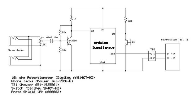
Have you ever wanted your home entertainment or sound system to power on automatically when plugging in your iPod or another portable MP3 player? To achieve automatic power activation of a home entertainment system when a portable device is...
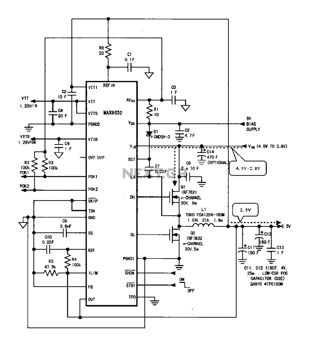
DDR memory power supply circuit. This circuit illustrates the power supply configuration for notebook DDR memory, utilizing the MAX8632 power control circuit chip. The power supply terminal VDD is connected to the voltage detection point 1. The battery DC...
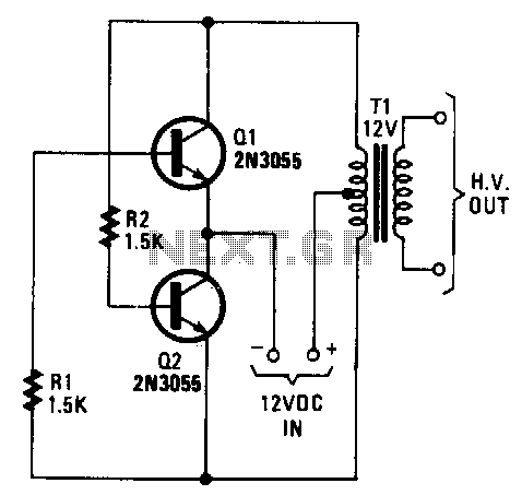
The transformer can be any 6.3 or 12.6 V type. Apply the 12-V DC input so the positive goes to the transformer's center tap and the negative goes to the two transistor emitters. Any bridge-type rectifier and filter can...
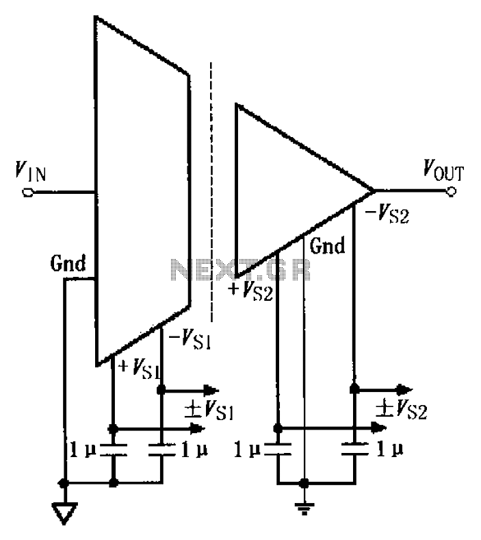
The basic connection circuit for the ISO122/124 includes power and signal connections. Each supply terminal of the ISO122/124 must be equipped with a 1 µF tantalum capacitor serving as a bypass filter. It is important to position the printed...
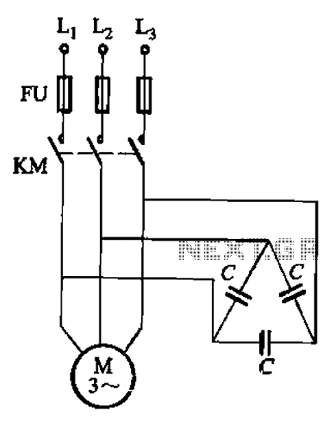
Asynchronous motor reactive power compensation involves directly connecting a capacitor to the stator windings of the asynchronous motor to enhance its power factor. This method is particularly effective for synchronous motors, as it reduces energy consumption related to reactive...