
pwm rectifier power controller
A PWM (Pulse Width Modulation) rectifier power controller is a sophisticated electronic circuit designed to convert alternating current (AC) to direct current (DC) while maintaining high efficiency and low harmonic distortion. This type of power supply utilizes PWM techniques to modulate the width of the pulses in the output waveform, allowing for precise control over the output voltage and current.
The circuit typically consists of several key components, including a rectifier bridge, PWM controller, filter capacitors, and an output load. The rectifier bridge, usually composed of diodes, converts the incoming AC voltage to pulsating DC. The PWM controller then regulates this pulsating DC by adjusting the duty cycle of the output signal, which in turn controls the average voltage delivered to the load.
In a typical configuration, the PWM controller receives feedback from the output voltage or current, allowing it to adjust the PWM signal dynamically. This feedback loop ensures that the output remains stable under varying load conditions. Filter capacitors are employed to smooth the pulsating DC output, reducing ripple and providing a more stable DC voltage to the load.
The design of the PWM rectifier power controller circuit can also include additional features such as over-voltage protection, under-voltage lockout, and thermal protection to enhance reliability and safety. The overall efficiency of this power supply design can reach upwards of 95%, making it suitable for applications requiring high performance and energy efficiency.
This power supply is commonly used in various applications, including renewable energy systems, electric vehicles, and industrial automation, where precise control and high efficiency are paramount. The circuit diagram associated with this power supply provides a visual representation of the interconnections and functionality of the components, facilitating better understanding and implementation of the design.PWM Rectifier power controller power supply. Go to that page to read the explanation about above power supply related circuit diagram. 🔗 External reference
Related Circuits

This article was originally published in a slightly modified form in the QST magazine, December 1998 and January 1999, and in the Radio Amateur's Handbook, 1999. Visit the American Radio Relay League for information on these publications and a...
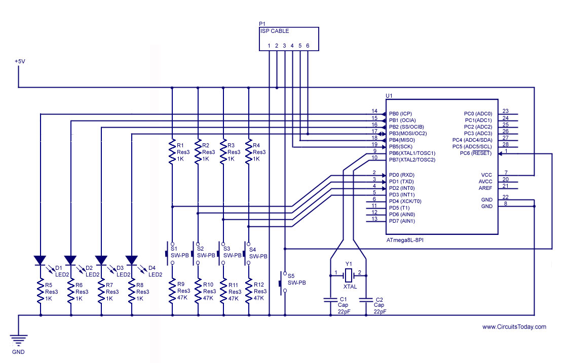
How to handle digital input/output (I/O) in AVR microcontrollers is explained using basic programs and circuits to illuminate an LED, generate a stepper motor sequence, read a push-button switch, and implement key debouncing. The handling of digital I/O in AVR...
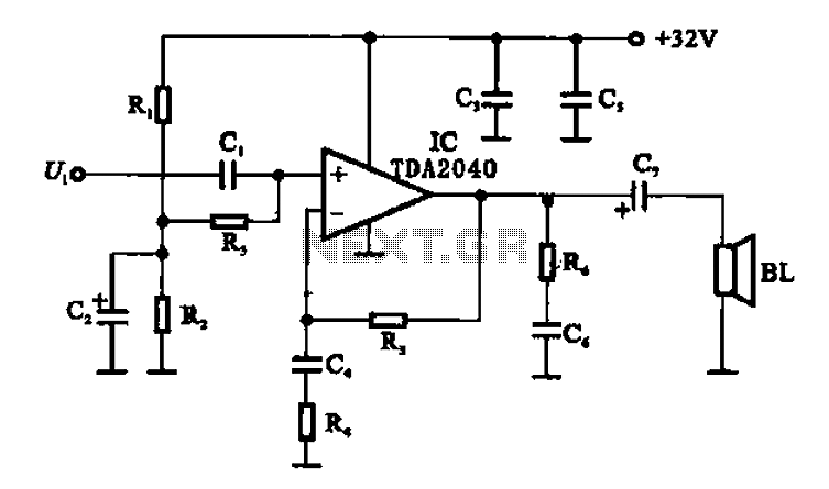
An integrated power amplifier TDA2040 is used in an OTL (Output Transformer-Less) power amplifier circuit, which operates with a +3V single supply as the working voltage. This circuit has a voltage gain of 30 dB (approximately 32 times magnification),...
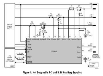
The LTC 4241 is a Hot Swap controller that enables safe insertion and removal of a board from a live PCI-bus slot. It features a primary controller that manages the four PCI supplies, along with an independent auxiliary controller...
The 555 oscillator operates with a +12V supply and ground, without the need for a -12V supply. The 555 timer IC is a versatile component commonly used in various oscillator and timer applications. In this configuration, the circuit is powered...
More: The input data lacks specific content, providing only placeholders without any detailed information. In the context of electronic schematics, a comprehensive description typically involves detailing the components, their interconnections, and the overall functionality of the circuit....