
Home Security System
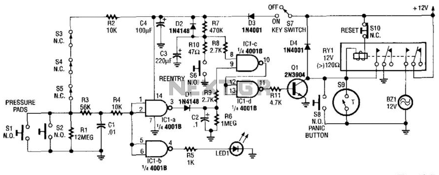
The described alarm circuit employs a series of switches (S1 to S5) that, when activated, initiate the alarm sequence. The activation of these switches sends a signal to LED1, which serves as a visual indicator of the alarm status. The signal is further processed by integrated circuits IC1C and IC1D, which control the operation of transistor Q1. This transistor acts as a switch to energize relay RY1, allowing it to latch and maintain the alarm state even after the initial activation signal is removed.
The self-latching feature of relay RY1 ensures that once the alarm is triggered, it remains active until a reset command is issued. This is accomplished through switch S10, which, when engaged, interrupts the current flow and resets the circuit to its initial state.
In scenarios where the key switch S1 is activated or the re-entry buttons S6 are pressed, the circuit design incorporates a delay mechanism through an RC network made up of resistor R7 and capacitor C3. This configuration temporarily deactivates IC1C, preventing immediate reactivation of the alarm. The time it takes for the capacitor C3 to charge through resistor R7 determines the delay period before the alarm can be re-engaged.
Overall, the alarm circuit is designed for reliability and user control, allowing for quick resets while preventing accidental reactivation during authorized re-entry situations. The combination of visual indicators, latching mechanisms, and delay circuits enhances the functionality and usability of the alarm system in various applications. This alarm circuit activates when SI through S5 are activated. This lights LED1 and activates Ql via IC1C and IC1D. RY 1 is wired to self latch. S10 is used to reset. When key switch SI is activated or when re-entry buttons at S6 are depressed, IC1C is deactivated until RC network R7/C3 charges. 🔗 External reference
Related Circuits
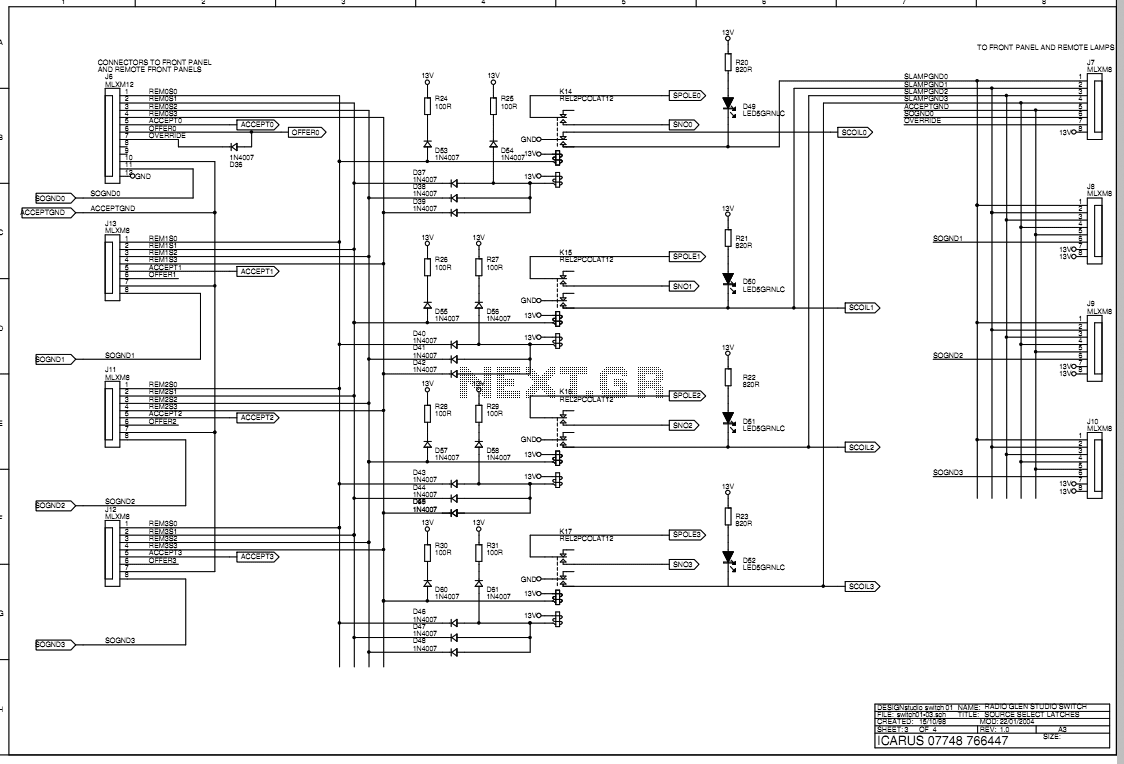
The main box of the Transmit Selector system is designed to be located in the technical rack of a small radio broadcast station. There are four stereo balanced line inputs, either of which can be routed to a stereo...
The circuit utilizes reed switches to create a gate alarm that is powered by a universal AC/DC power supply oscillator. The design of this gate alarm circuit incorporates reed switches, which are electromechanical devices that operate based on the presence...
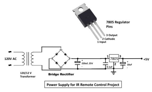
The infrared (IR) toggle switch project aims to provide a control mechanism for electrical appliances lacking remote operation features. The objective is to create a device that allows users to plug in a 120V AC appliance and control its...
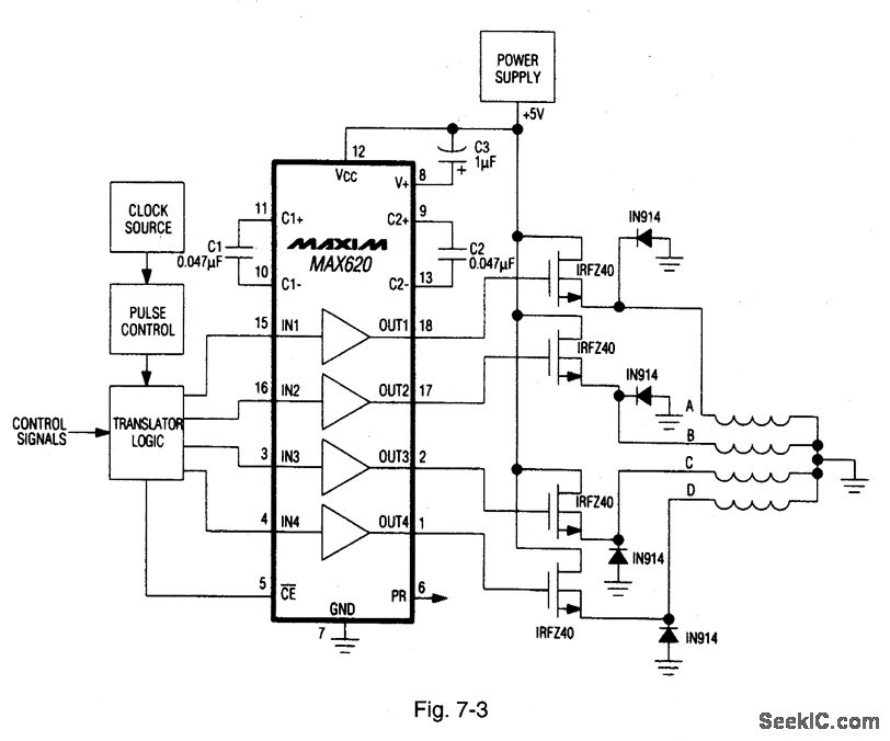
A MAX620 is connected to create a complete stepper motor drive system. TTL/CMOS signals from the logic network are converted to high-side levels that control four N-channel power MOSFETs, which supply current to each of the four phases of...
1990 Acura Integra Starting System Wiring Diagram. The 1990 Acura Integra starting system wiring diagram provides a visual representation of the electrical connections and components involved in the vehicle's starting system. This diagram is essential for understanding the layout and...

This intermediate frequency (IF) system employs a NE602 oscillator/mixer to convert VHF television signals ranging from 60 to 72 MHz (channel 13 or channel 4 under the U.S. NTSC standard) down to 45 MHz. A surface acoustic wave (SAW)...
Warning: include(partials/cookie-banner.php): Failed to open stream: Permission denied in /var/www/html/nextgr/view-circuit.php on line 713
Warning: include(): Failed opening 'partials/cookie-banner.php' for inclusion (include_path='.:/usr/share/php') in /var/www/html/nextgr/view-circuit.php on line 713