
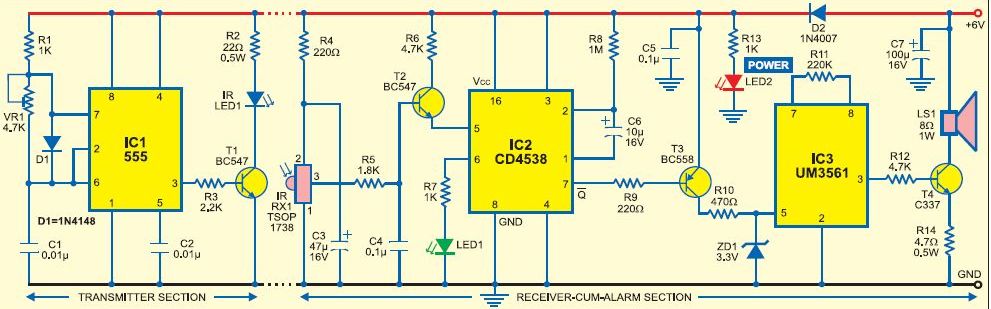
Alarm System for Entrance/Exit Gate
The design of this gate alarm circuit incorporates reed switches, which are electromechanical devices that operate based on the presence of a magnetic field. When a magnet approaches the reed switch, it causes the contacts within the switch to close, completing the circuit. This action can trigger an alarm or notification system, making it suitable for use in gate security applications.
The power supply for this circuit is a universal AC/DC power supply oscillator, which is capable of converting alternating current (AC) from the mains into direct current (DC) suitable for powering electronic components. This versatility allows the circuit to operate under various voltage and frequency conditions, making it adaptable to different geographical locations.
The oscillator component of the power supply is crucial for maintaining a stable voltage output, ensuring that the circuit functions reliably. In addition, it may include features such as voltage regulation and protection against overcurrent or short circuits, enhancing the safety and longevity of the circuit.
To implement this circuit, careful consideration must be given to the placement of the reed switches and the magnet to ensure optimal performance. The reed switches should be mounted in a way that they are activated only when the gate is opened or closed, preventing false alarms. Furthermore, the alarm system can be enhanced by integrating additional features, such as a delay timer or an indicator light, to provide visual feedback when the alarm is triggered.
Overall, this gate alarm circuit represents a practical application of reed switch technology in security systems, leveraging a universal power supply for versatility and reliability.The circuit employs the functions of reed switches to produce a gate alarm that is powered by a universal AC/DC power supply Oscillator an electronic ci.. 🔗 External reference
Related Circuits
This simple AVR programmer is capable of transferring hex programs to most ATMEL AVR microcontrollers. It is more reliable than many other simple AVR programmers available and can be constructed in a very short amount of time. This programmer...
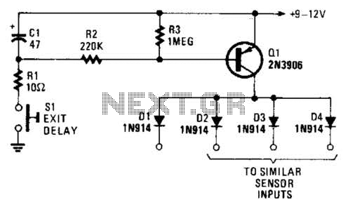
Depressing SI charges CI to the supply voltage. This biases Q1 on via bias resistors R2 and R3. A voltage is available for the duration of the delay period to hold off the alarm circuit. CI can be increased...
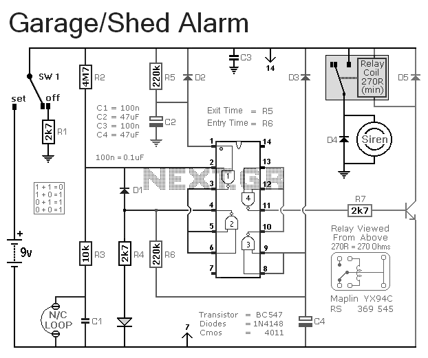
This is a simple single-zone burglar alarm. The basic design includes automatic exit and entry delays. It does not include a siren cut-off timer, but with a small modification, one can be added to the circuit. The alarm will...
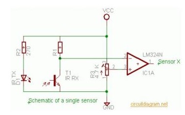
This burglar alarm system circuit utilizes an infrared proximity detector that triggers an alarm when the rays falling on its sensor are interrupted. It stands out from other burglar alarm systems due to its simplicity as a DIY project,...
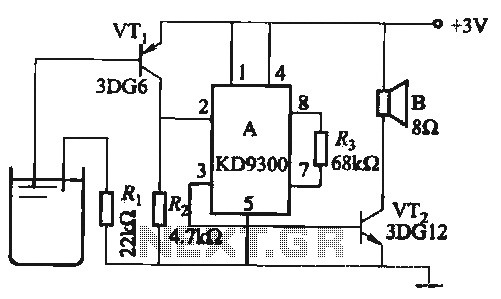
Changing the values of Ri, R2, Cl, and C3 can modify the alarm tone. The circuit utilizes KD9300 music integrated circuits. The circuit described is designed to generate an alarm tone through the manipulation of specific component values within the...
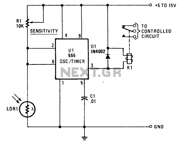
LDR1, a cadmium sulfide (CDS) photoresistive cell, is utilized as the lower leg of a voltage divider between Vcc and ground. The timer terminals 2 and 6 are connected to the junction of the photocell and the sensitivity control...