
Radio Glen Transmit Selector system
As noted the latching relays are non-volatile; They remain in their last position when power is disconnected. The signal switching relays are ordinary non-latching types however. The system is designed such that the switcher will revert to the sustain programme input on channel one when power fails. When power is restored, the originally selected studio will be put back to the transmitter.
The Transmit Selector system serves as a critical component in a radio broadcast station, facilitating the seamless transition between various audio sources. The architecture consists of a main unit and multiple remote control panels, interconnected via a robust sixteen-way cable system. The main box accommodates four stereo balanced line inputs, enabling versatile signal routing through mechanical relays. These relays, while effective, introduce audible switching noise, which is a consideration during operation.
Control is achieved through a user-friendly interface, with four buttons available on the main unit and identical buttons on remote panels. The system employs an offer-accept protocol, where only the panel with an illuminated 'ACCEPT' lamp can control the routing. This design enhances operational flexibility, allowing for quick changes in control should the need arise. The inclusion of an 'OVERRIDE' button on the main panel provides an additional layer of control, allowing it to regain authority over the system regardless of the current selection state.
The system's design incorporates latching relays that retain their state during power loss, ensuring that the last selected input is preserved. In contrast, the signal routing relays are non-latching, defaulting to the first channel input upon power restoration. This feature is critical for maintaining a consistent broadcast feed.
The power supply unit (PSU) is designed to deliver stable voltage to the system, with provisions for voltage dropping diodes to manage power levels effectively. The choice of a toroidal transformer is recommended to minimize electromagnetic interference, which is particularly important in audio applications.
The rear panel features a 25-way D connector for interfacing with external devices, including triac units for driving large annunciator lamps. These lamps serve as visual indicators for on-air status and control states, enhancing the operator's situational awareness. The system's architecture ensures that only one remote panel can assert control at any time, facilitated by a diode ORing arrangement that prevents multiple panels from interfering with one another.
Overall, the Transmit Selector system is engineered to provide reliable, user-friendly control over audio routing in a broadcast environment, ensuring operational efficiency and clarity in signal management.The main box of the Transmit Selector system is designed to be located in the technical rack of a small radio broadcast station. There are four stereo balanced line inputs, either of which can be routed to a stereo balanced output.
The signal routing is performed with relays and so the switching may not be completely silent. The source is selected by one of four buttons on the main box or by an identical pattern of buttons on one of three remote control panels. The particular panel which can control the switcher at any time is the panel which has the 'ACCEPT' lamp lit.
This works on the standard offer-accept system as widely used on mixing desks and switchers. The main switch unit also has an 'OVERRIDE' button which can be used to force the system into offer mode regardless of whether the main panel has control. The main panel can therefore steal control when needed, and this also serves to reset the system on delivery or when the latching relays have been set to an unknown state by vibration in transit. Also, if a remote panel has control and is subsequently disconnected, the system can still be switched from the main panel using override.
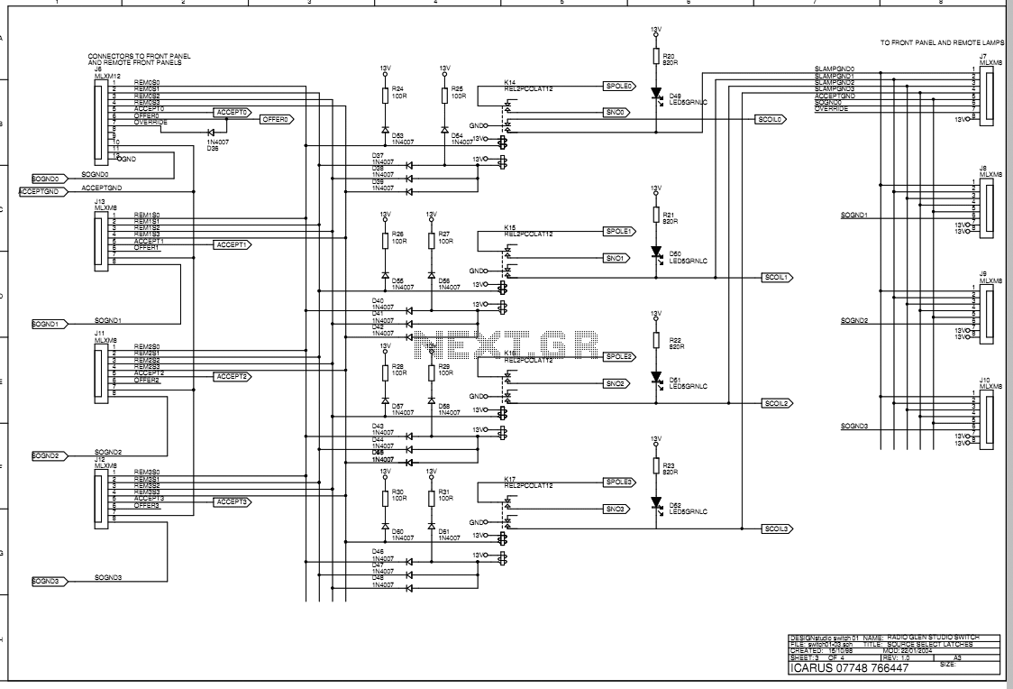
Remote panels connect to the main unit via a sixteen way cable terminated with 25-way D-connectors. All power for remote lamps is provided along this cable. Both main units and remote panels are 2U size, though this is only due to handy small boxes for the remotes only being available in 2U size. Future units could be 1U if suitable hardware can be found. The main unit will have to remain 2U due to the number of connectors on the rear panel. All switch lamps are LED types. Sheet two has the four state relays which record which panel has control, ie the accept lamp lit. The common ground of each remote panel's select switches are routed through the appropriate relay, so only one remote has control.
The fifth relay on the sheet indicates the offer state and allows any remote panel to alter the state of the accept relays. Note that when one panel selects its own accept relay to go on, it switches all the others off via the diode ORing arrangement, ensuring that only one panel can ever accept control.
SOGNDx is a potentially confusion label; It stands for SELECT/OFFER GND and is low for the panel which has the accept lamp. In this state that panel can both do selecting and offering. This is the PSU and the outputs to the triac system connector. The PSU is self explanatory, other than the voltage dropping diodes. In an ideal world you would select the correct voltage of transformer to start off with, though the choice of a toroid is always a sensible option with audio equipment.
Each of the state relays' second normally open contact pair are taken off to a 25-way D connector on the rear panel. This can be used to switch a triac unit to light large mains annunciator lamps to indicate who is on air, who has switch control, and when switch control is on offer.
As noted the latching relays are non-volatile; They remain in their last position when power is disconnected. The signal switching relays are ordinary non-latching types however. The system is designed such that the switcher will revert to the sustain programme input on channel one when power fails.
When power is restored, the originally selected studio will be put back to the transmitter. 🔗 External reference
Related Circuits
The schematic presented is a circuit for a 555 tracking transmitter. The 555 timer is a well-known versatile integrated circuit utilized in various electronic projects. In the circuit described, this IC generates a tone that is transmitted through an...
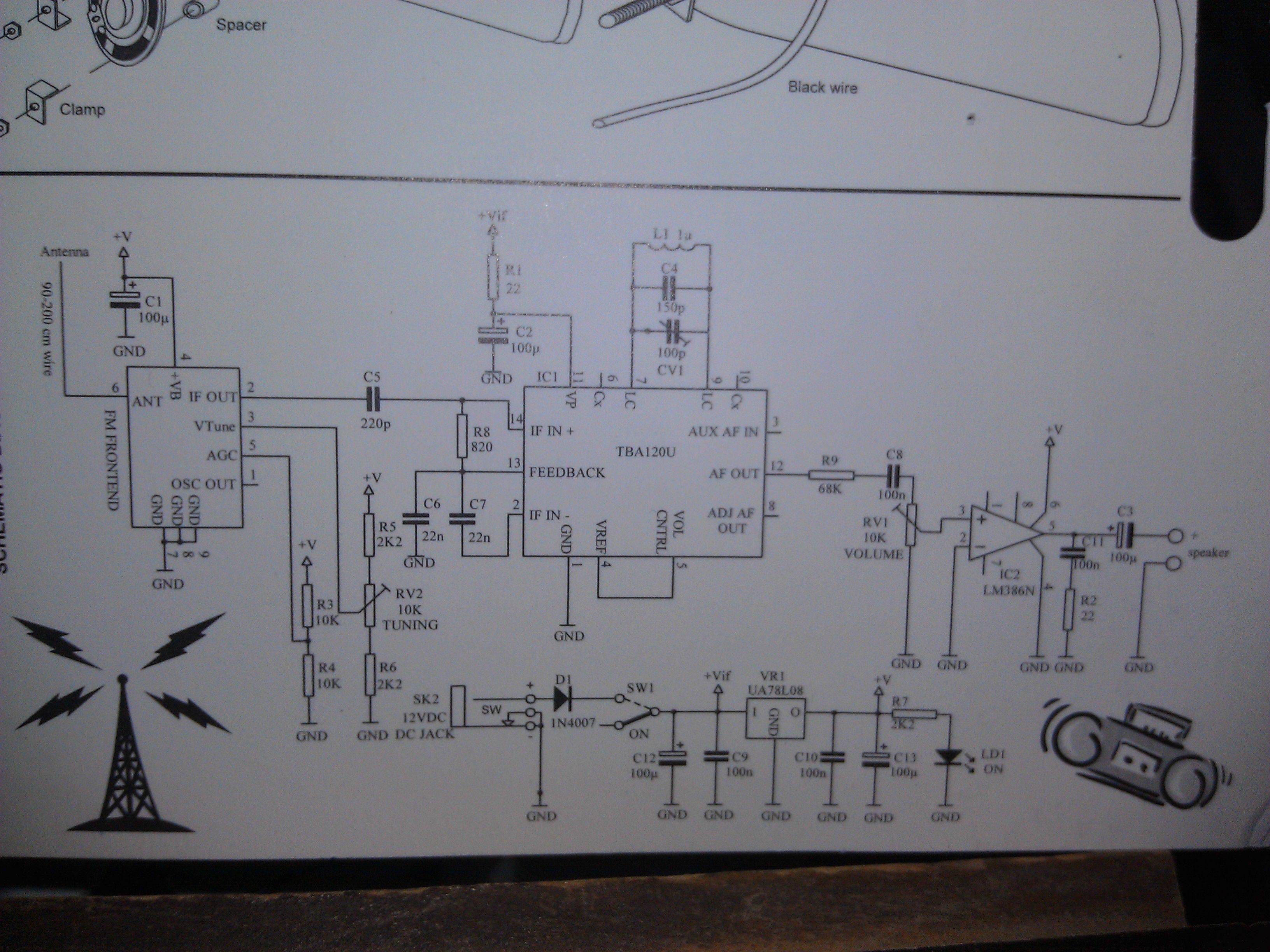
An FM Radio kit manufactured by Velleman-Kit and sold by Radioshack was recently assembled. The assembly process took approximately two hours, primarily due to distractions. The instructions provided are generally easy to follow, but they lack explicit details regarding...
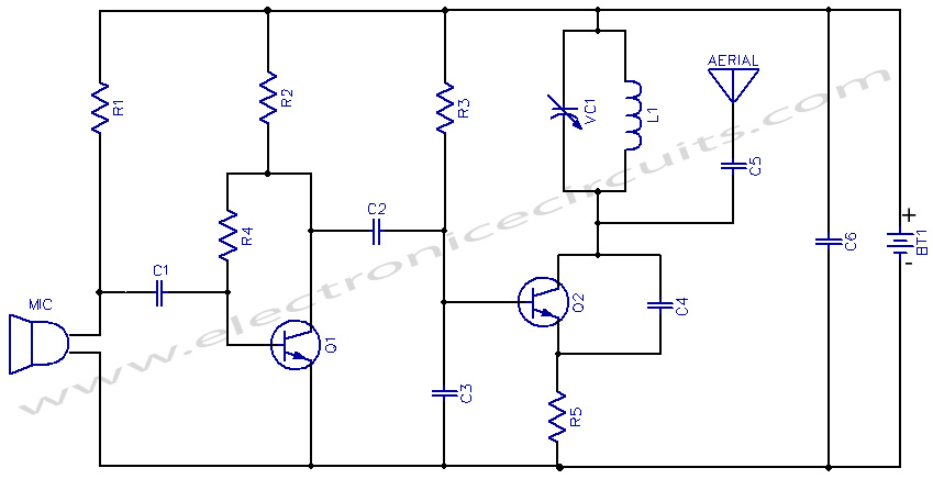
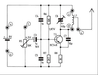
This project provides the schematic and the parts list needed to construct a 3V FM transmitter. This FM transmitter is one of the simplest and most basic transmitters to build, yet it offers a useful transmitting range. It is...
The circuit presented is a straightforward yet efficient amplifier that can provide notable performance enhancements. This amplifier can demonstrate negative resistance at lower settings of the 500-ohm potentiometer, resulting in increased gain or even oscillation. Consequently, the circuit can...
Electronics-DIY provides instructions for constructing a simple portable FM transmitter that enables an iPod to broadcast music over radio waves. The assembly is straightforward and can be housed within a mouse case. The device operates easily, featuring a power...
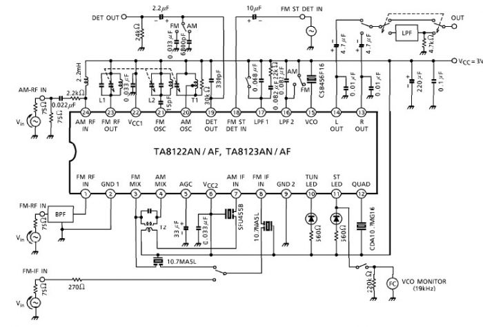
A simple low-power AM/FM radio receiver electronic project can be designed using the TA8122 integrated AM/FM receiver, manufactured by Toshiba Semiconductor. This radio receiver circuit is suitable for portable radio applications or other similar devices. The TA8122 radio receiver...