
Homebuilt arc welder
The arc welder is a vital tool in metalworking that utilizes an electric arc to melt and join metal components. The design typically includes a power supply, an electrode holder, a workpiece clamp, and a control circuit. The power supply can be either transformer-based or inverter-based, depending on the desired welding characteristics and portability.
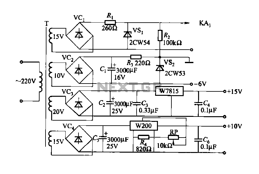
The schematic should include a transformer or inverter circuit that converts standard AC voltage to the required welding voltage. The output current can be adjusted using a variable resistor or a digital control interface. Safety features such as circuit breakers and thermal protection should be integrated to prevent damage to the welder and ensure user safety.
The electrode holder should be designed to securely grip the welding electrode while allowing for easy replacement. The workpiece clamp must provide a stable connection to the metal being welded, ensuring proper current flow. Additionally, a cooling system may be implemented to dissipate heat generated during welding, prolonging the life of the components.
The control circuit should include indicators for power status, current adjustment, and any fault conditions. Proper grounding and isolation techniques must be employed to minimize electrical hazards. Overall, the arc welder's design should prioritize efficiency, safety, and ease of use for optimal performance in various welding applications.Build your own arc welder! Many of you have been so patiently waiting the arrival of these DETAILED PLANS that you can purchase and download (4. 6MB pdf!)for a small fee. 🔗 External reference
Related Circuits
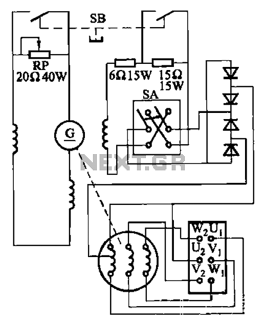
The AX3-300-2 DC arc welding machine circuit is part of the AX, AX1, AX3, and AR series of rotary DC arc welding machines. These machines share a similar structural design, featuring a three-integral unit configuration that combines an inverter...
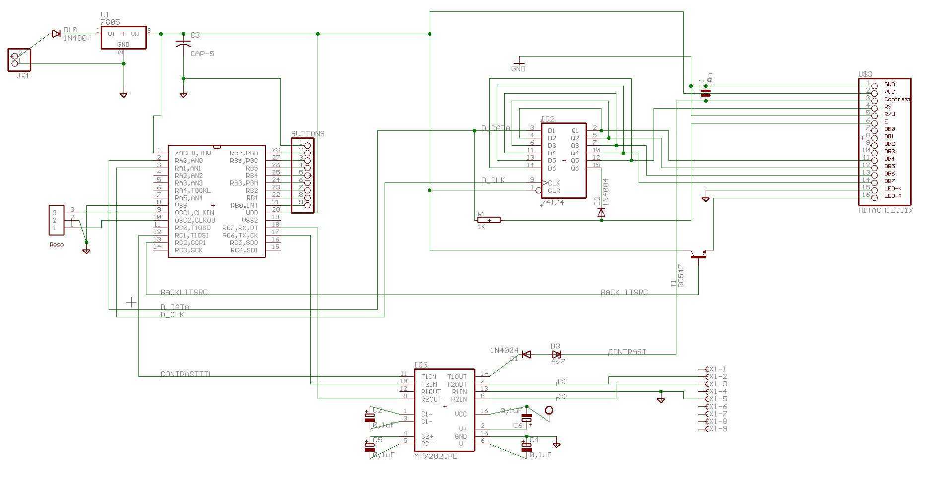
There is enough of poorly constructed RS232 alike TTL level interfaces (+5volt), this one generates its own +/- 10..11 volts as RS232 specs require, and is able to use very long cables like RS232 can, and protects computer as...
An 80m (3.5 - 3.9 MHz) SSB transceiver utilizes a Collins 455 kHz mechanical filter in the intermediate frequency (IF) chain. Such designs require effective front-end receiver selectivity, typically achieved through the inclusion of at least two selective tuned...
This document outlines a CMOS circuit designed for time adjustment in a spot welder. The circuit allows for the selection of a number of cycles, ranging from 1 to 99, with practical applications typically using around 10 cycles. The...
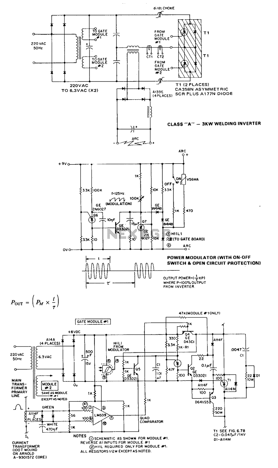
The Class A series resonant inverter is recognized for its high efficiency, low cost, and compact size, provided the operating frequency exceeds approximately 3 kHz. However, it faces challenges, particularly in high power versions, regarding the difficulty of achieving...
For example, I do not understand the process of demodulation or the modulation itself, and so on. Is there someone who can understand this circuit? Could you please assist me? The circuit in question likely involves a modulation and demodulation...