
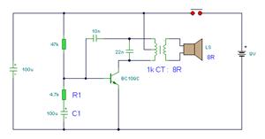
Homemade 20W fluorescent lamp dimmer circuit diagram

The circuit design for the homemade fluorescent lamp dimmer includes a basic arrangement of components that facilitate the adjustment of light intensity. The primary component is a capacitor, which is connected in series with the fluorescent lamp. This configuration allows for the reduction of current flowing through the lamp, thereby dimming its brightness.
The switch used in the circuit serves a dual purpose. In position 1, it completes the circuit for normal operation, allowing the lamp to receive full power and emit standard brightness. In position 2, the switch alters the circuit's configuration to include the series capacitor, which decreases the voltage across the lamp, resulting in increased brightness.
Additional components may include a resistor for current limiting, ensuring that the fluorescent lamp operates within safe parameters. Proper selection of the capacitor value is crucial, as it directly affects the dimming range and the stability of the lamp operation. The circuit should be designed with safety in mind, incorporating appropriate insulation and ensuring that all components are rated for the expected voltage and current levels.
Overall, this dimmer circuit provides a simple yet effective solution for controlling fluorescent lamp brightness, making it suitable for various applications where adjustable lighting is desired.Homemade 20W fluorescent lamp dimmer Using the method of connecting capacitor in series can easily control the brightness of fluorescent lamps. To adapt to different lighting requirements. Figure 28 is a modified circuit diagram. When the switch connects to the 1, the brightness of the lamp is normal, the actual power is 20w; and connects to 2, bright..
🔗 External reference
Related Circuits

This schematic is directly sourced from the Altera ByteBlaster datasheet or manual, which provides comprehensive details regarding the connector's functionality and pin connections. It is advisable to review the datasheet available on their website or through a search engine...
This electronic pressure gauge utilizes a Wheatstone bridge-type pressure sensor to drive a 3 A digit A/D converter and a display. IC1 is a quad op-amp that interfaces the bridge sensor to the A/D converter. R16 allows for zero...
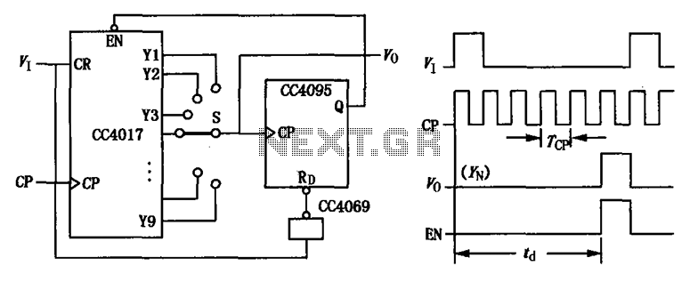
CC4017 counter/distributor featuring a circuit diagram of the delay. The CC4017 is a decade counter and distributor that counts from 0 to 10, providing ten output states. It is commonly used in various digital applications for counting purposes, such as...
This is the complete wiring diagram for the 1997 Honda CR-V. It includes wiring diagrams for each electrical module of the Honda CR-V, such as the Rear Wiper/Washer Circuit, Front Wiper/Washer Circuit, Warning System Circuits, and the Supplemental Restraint...
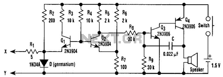
The simple bell circuit without IC. It includes a doorbell circuit that can produce different sounds using integrated circuits, transistors, and resistors. The circuit utilizes a coded trigger mechanism to differentiate between various visitors. When the button is pressed,...
Several RS232 transceiver circuits are used for communication between microcontrollers and other devices, such as PCs or RS232 devices. This document presents a collection of well-known RS232 transceiver circuits. The circuit utilizes the MAX232 from Maxim's devices, which is...