
Delay circuit diagram CC4017 counter divider consisting
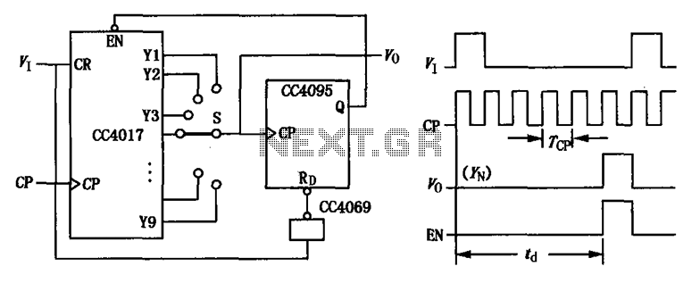
The CC4017 is a decade counter and distributor that counts from 0 to 10, providing ten output states. It is commonly used in various digital applications for counting purposes, such as in timers, clocks, and event counters. The device operates on the principle of binary counting, where each output represents a specific count state.
The circuit diagram typically includes the CC4017 IC, which has ten output pins (Q0 to Q9) and a clock input. The clock input triggers the counting sequence, while the reset pin allows the counter to return to zero. The delay aspect of the circuit can be implemented using additional components such as resistors and capacitors, which form an RC timing circuit. This timing circuit can introduce a delay in the clock signal, allowing for controlled counting intervals.
In practical applications, the outputs of the CC4017 can be connected to LEDs to visually indicate the count or to other digital circuits for further processing. The use of the reset feature allows for the counter to be restarted at any time, making it versatile for various timing and counting applications. The design of the circuit must ensure that the power supply voltage is within the specified range for the CC4017 to function correctly, typically between 3V and 15V. Proper bypass capacitors should also be included to stabilize the power supply and prevent noise from affecting the performance of the counter. CC4017 count/distributor consisting of a circuit diagram of the delay:
Related Circuits
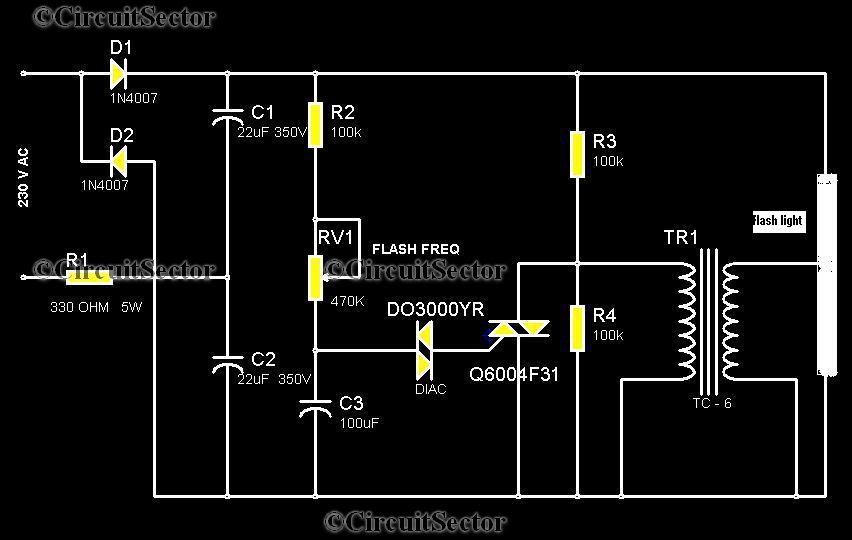
This circuit is a strobe light that allows for adjustable flashing rates. It utilizes a flash tube commonly found in cameras. In standard cameras, the flash may take ten to twenty seconds to recharge. However, this circuit enables the...
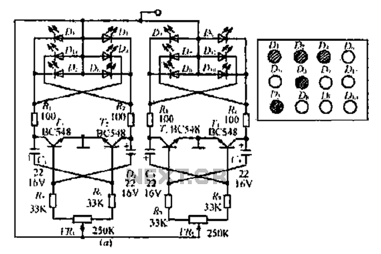
A circuit involving oscillations is composed of a Houle Wang oscillator that utilizes a transistor configuration with components labeled Ti, n, and n, along with a composition of Q constants for the cycle. The waveform can be modified by...
The circuit-delay relay for speakers serves as a delay mechanism that prevents the immediate activation of speakers when the amplifier is powered on. This feature is designed to protect the speakers from potential damage caused by sudden power surges....
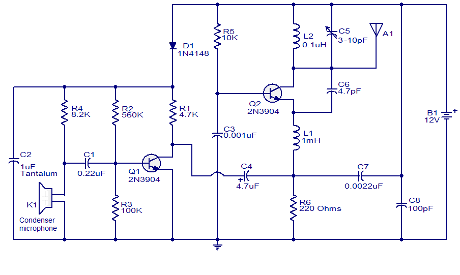
The FM transmitter circuit presented is both stable and simple. With an adaptive antenna, it can achieve a transmission range of approximately 200 meters. This transmitter was developed this year and has yielded positive results. The circuit operates using...
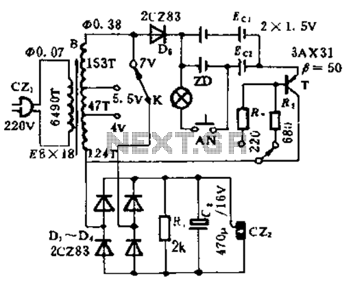
This circuit is designed for high current applications using nickel-cadmium rechargeable batteries, and it can also function as a general low-voltage DC power supply. The circuit consists of a charging section and a DC output section. K2 serves as...
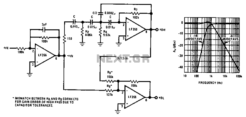
Asymmetric third-order Butterworth active crossover network circuit diagram. The asymmetric third-order Butterworth active crossover network is a sophisticated circuit designed to split an audio signal into two separate frequency bands, typically for use in multi-way speaker systems. This type of...