
Homemade metal detector
The metal detector circuit primarily consists of a signal generator, a detector coil, and a signal processing unit. The signal generator creates an oscillating electromagnetic field through the L1 coil, which is typically made of enameled copper wire wound around a non-magnetic core. When the detector coil passes over a metallic object, the magnetic field induces eddy currents in the object, which in turn generate their own magnetic field. This phenomenon is known as electromagnetic induction.
The circuit can be further enhanced by incorporating a microcontroller or an operational amplifier to process the signal received from the detector coil. The output can be connected to an audio feedback system, such as a buzzer or speaker, which alerts the user when a metallic object is detected. Additionally, a visual indicator, like an LED, can be included to provide a visual cue alongside the audio signal.
To ensure optimal performance, it is important to tune the circuit's sensitivity and frequency response. This can be achieved by adjusting the values of capacitors and resistors in the signal processing unit. Proper calibration will enhance the detector's ability to discern between different types of metals and minimize false positives from environmental noise.
The power supply, consisting of two 9V batteries, should be connected in series to provide a total voltage of 18V. It is advisable to use fresh batteries to maintain consistent performance, as voltage drops can affect the sensitivity of the detector. The circuit layout should be designed to minimize interference from external electromagnetic sources, ensuring reliable operation in various environments.
Overall, this homemade metal detector circuit is a practical project for electronics enthusiasts, providing a hands-on opportunity to understand the principles of electromagnetic induction and signal processing in detecting metallic objects.This homemade metal detector circuit will help you find objects composed of materials with relatively high magnetic permeability. It is not suitable for buried coins discovery that is not sensitive enough but you can detect pirates treasures!
The metal detector is powered by 2 x 9V batteries, each of it charges with 15 mA. L1 detector coil is part of the si.. 🔗 External reference
Related Circuits
The metal detector circuit consists of several key components including the probe oscillator, reference oscillator, oscillation signal processor, mixing amplifier, and ammeter PA. The probe oscillator is made up of the oscillating tube VI, exploration coil L1, capacitors C1...
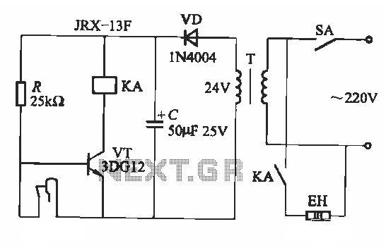
A fluorescent starter bimetal can be utilized as a temperature sensing element for thermostatic control. This component consists of a double metal sheet designed for temperature sensing, resulting in a simple circuit that is easy to manufacture, although it...
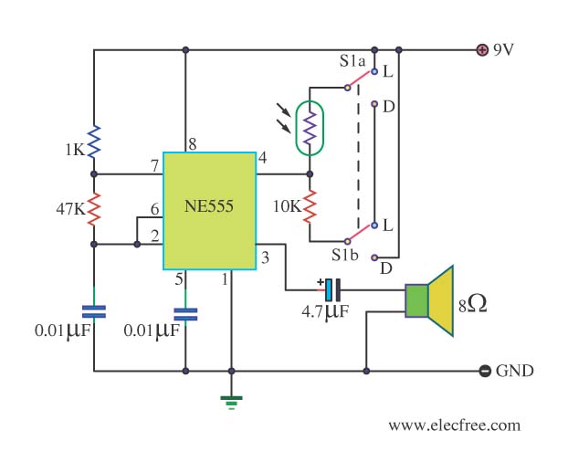
This circuit detects light and provides a voice warning. It responds to changes in light conditions, becoming active based on the position of switch S1. The circuit utilizes a light-dependent resistor (LDR) to sense ambient light levels. When the light...
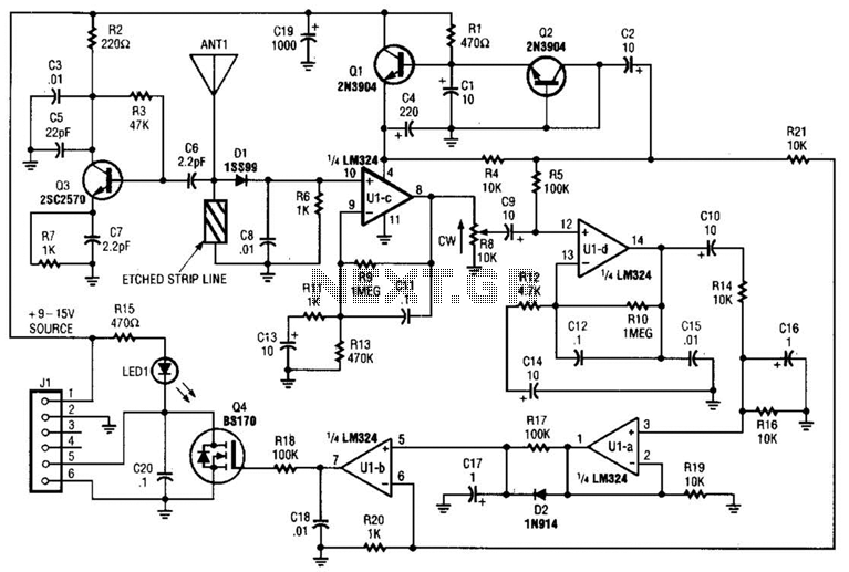
Operating at approximately 1.1 GHz, the detector senses disturbances in the electromagnetic field surrounding the antenna. The Doppler signal generated by detector D1 is amplified and used to control a power MOSFET switch. The antenna consists of a short...
This rain detector provides immediate notification when it begins to rain, allowing time to close windows and secure belongings. Alternatively, a molded power supply with a simple voltage regulator can be employed to reduce the voltage to 3 volts....
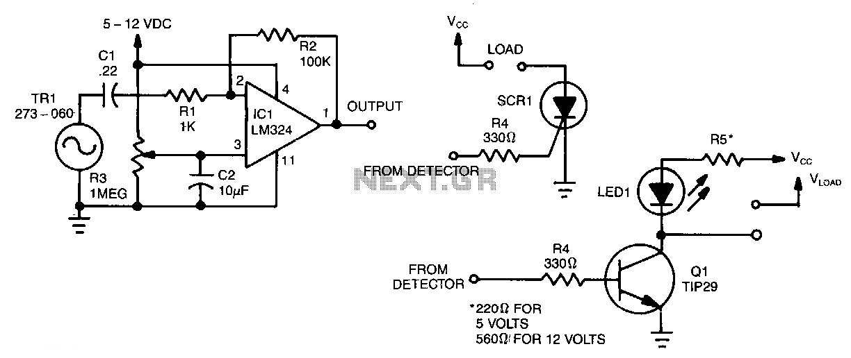
When a current of air strikes the piezo element, a small signal is generated and transmitted through C1 and R1 to the inverting input pin 2 of one section of the LM324. This action causes output pin 1 to...